1. 1wire
1wire is a browser-based drawing program for electricians to draw a single-line diagram and floor plan of electrical installations quickly and easily.
Because 1wire runs entirely in the browser, no installation is needed. You open the application via app.1wire.be in a modern browser and you can get started right away. When you're signed in, your projects are saved to the cloud automatically. Without an account you can still try out the editor, but you're working temporarily and locally in your browser.
Two ways of working
Way 1: Starting with the single-line diagram
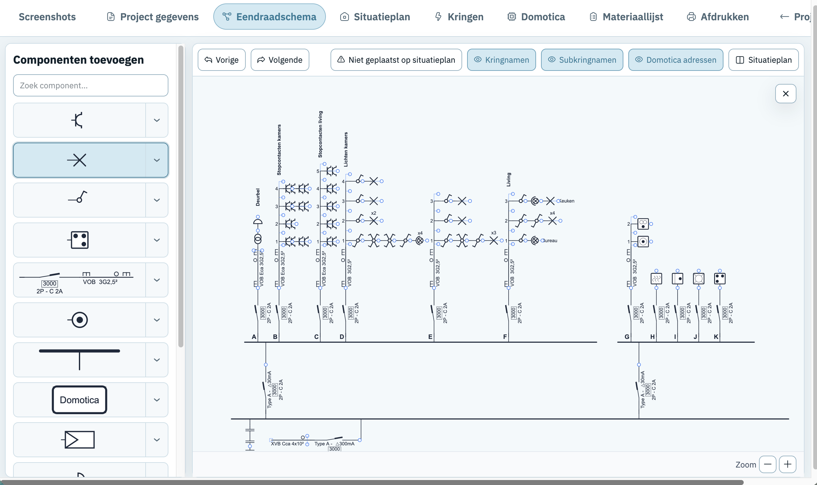
- Start with the single-line diagram. Select symbols from the library and add them to the diagram.
- Then draw the layout of the home or import an existing layout from an image or PDF.
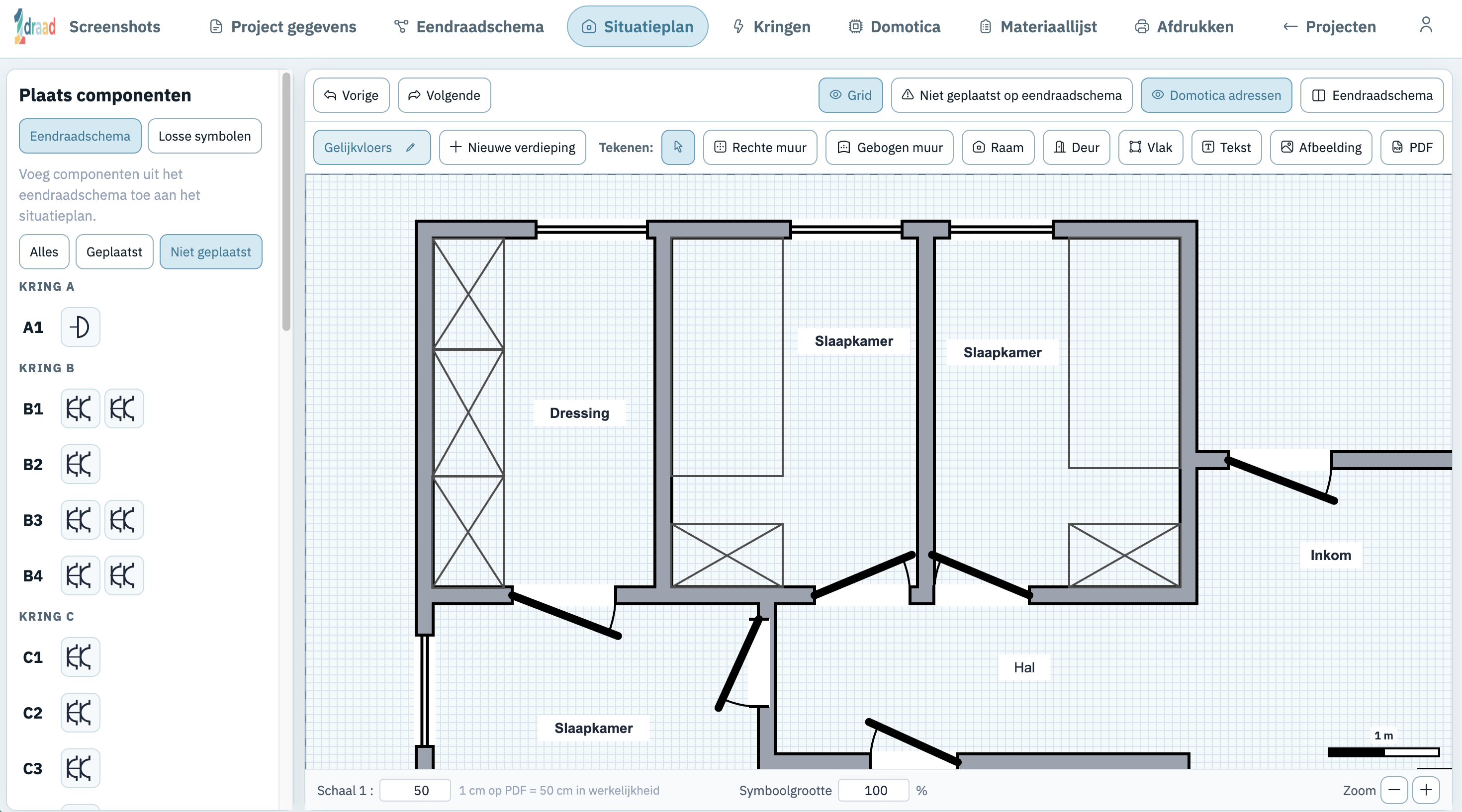
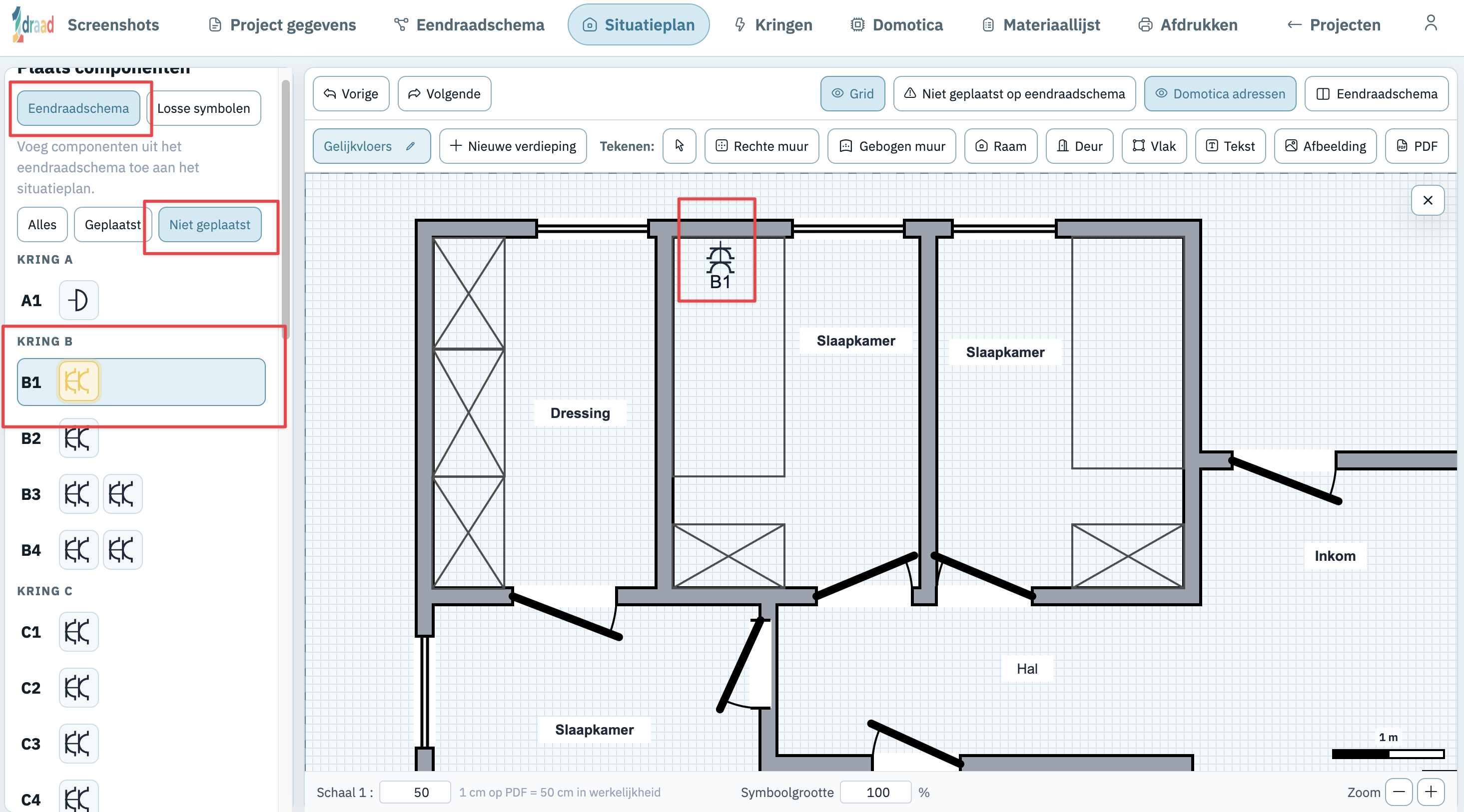
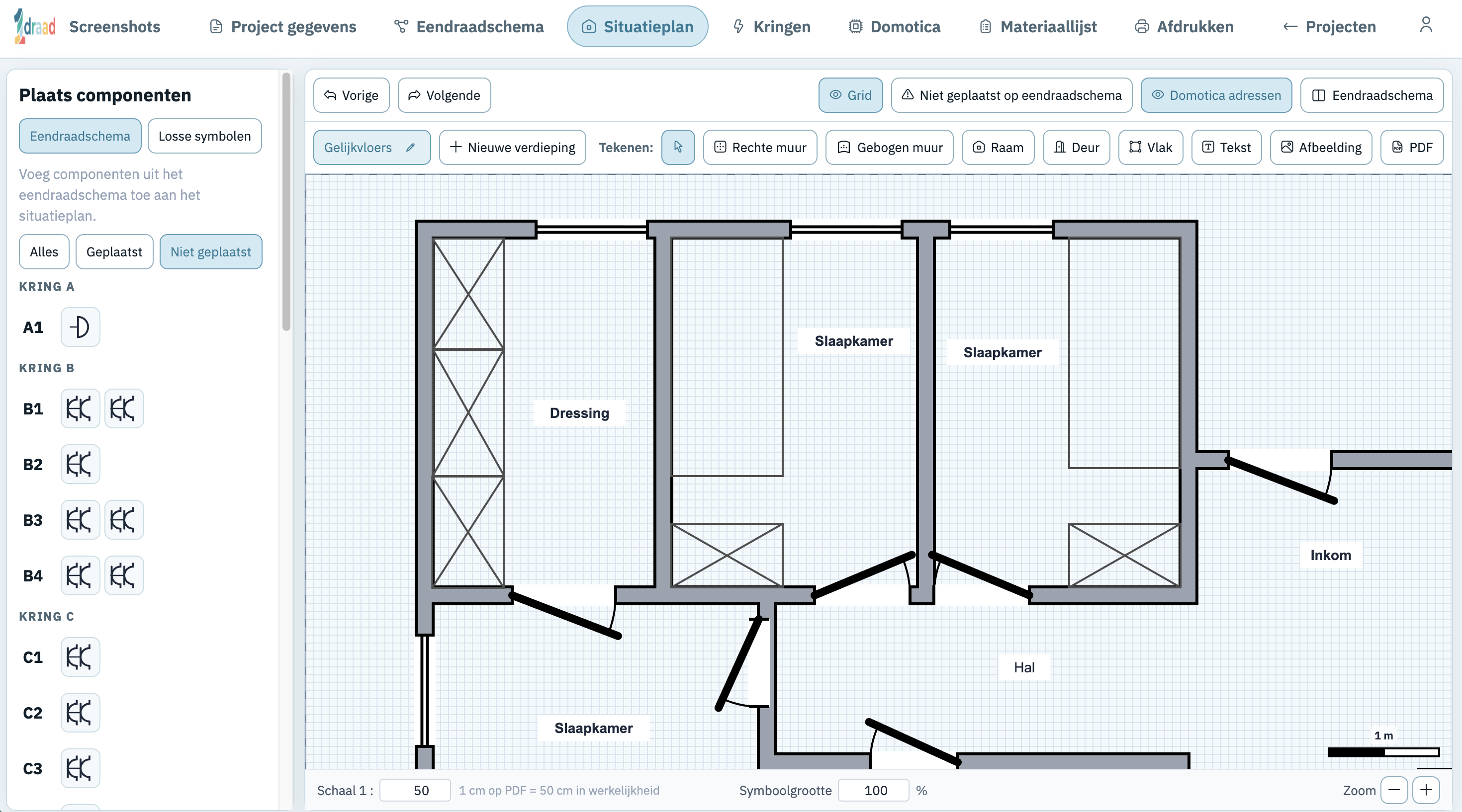
- The symbols you used in the single-line diagram appear to the left of the drawn floor plans, and you place them on the floor plan with a simple click.
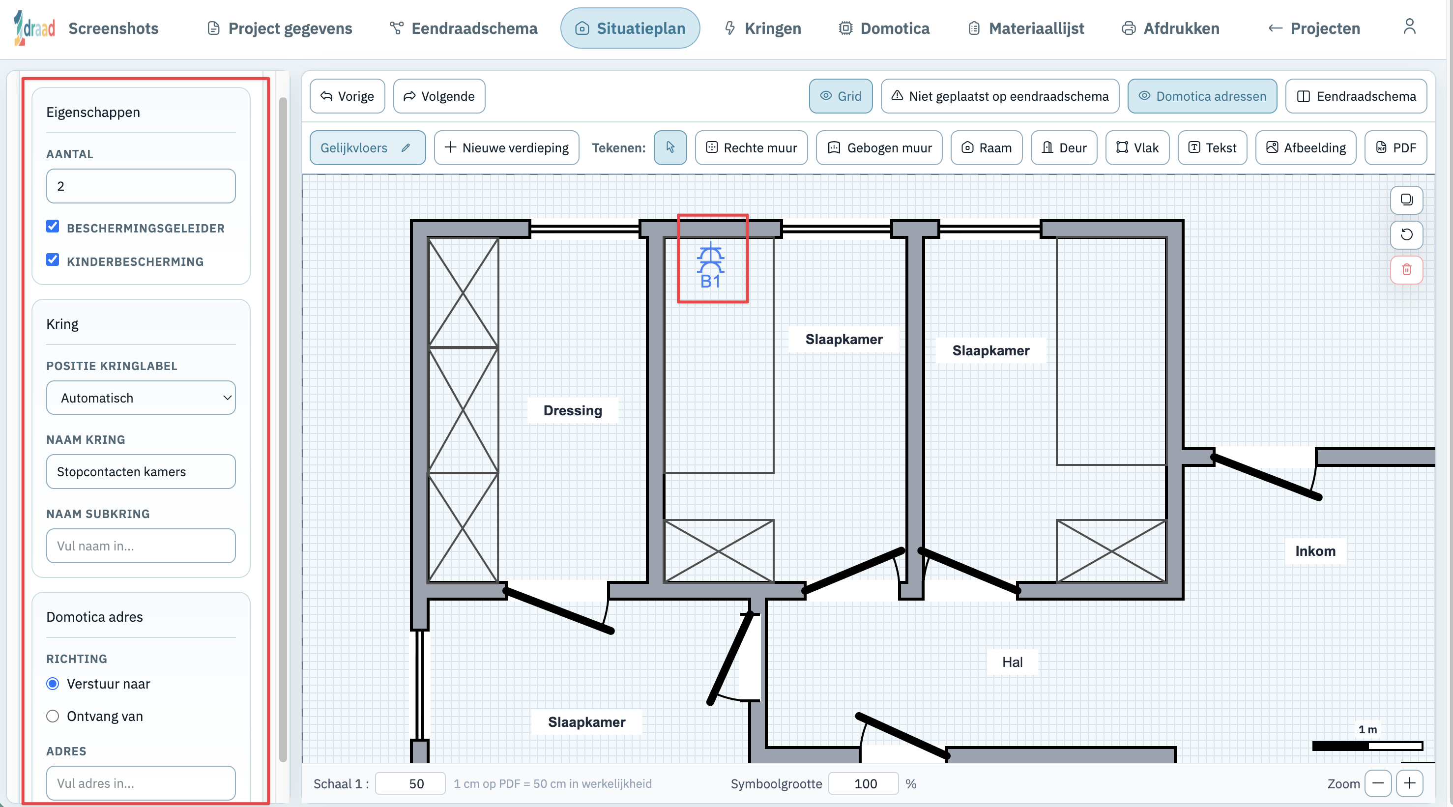
- You can adjust a symbol by changing its properties. The floor plan and single-line diagram always stay in sync.
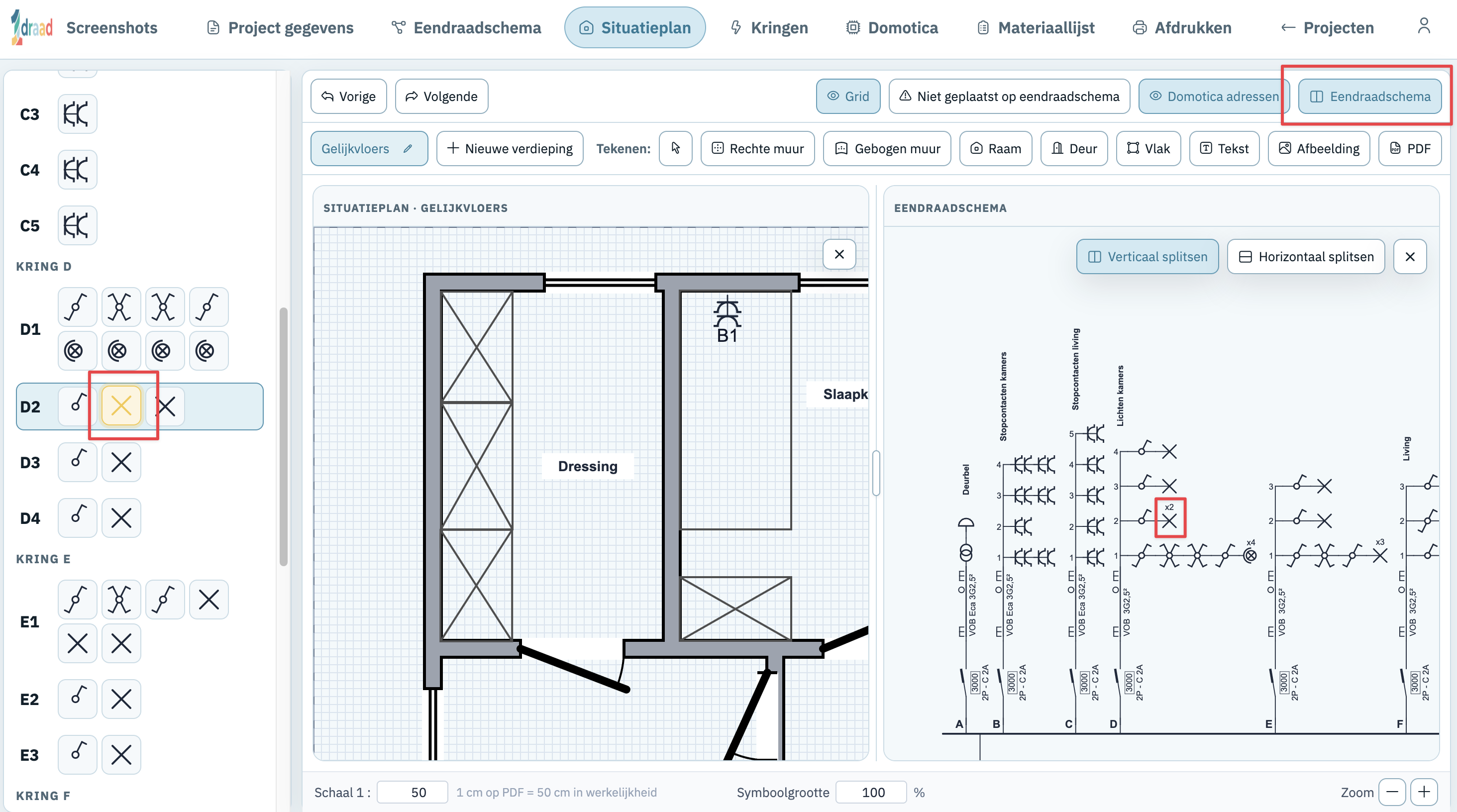
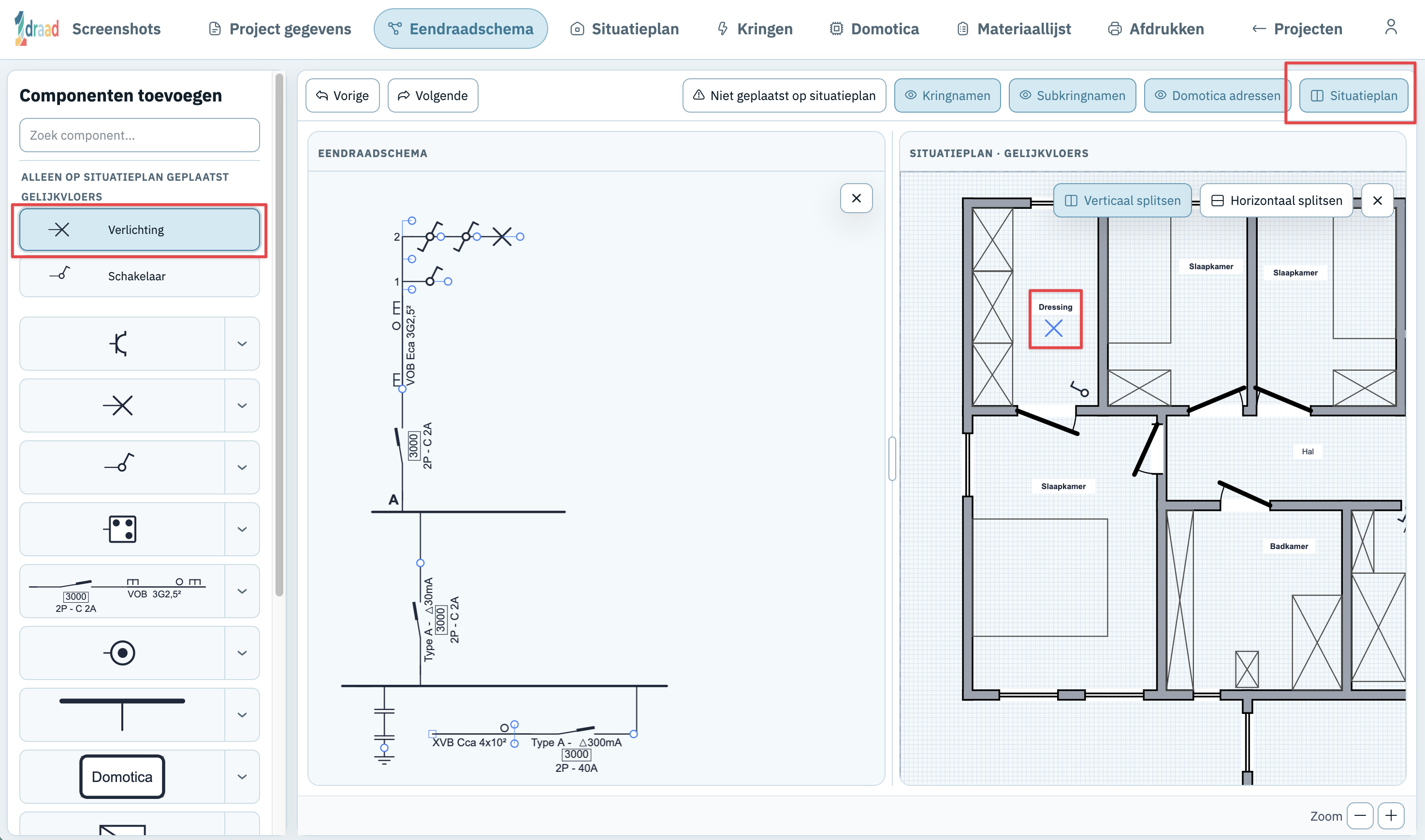
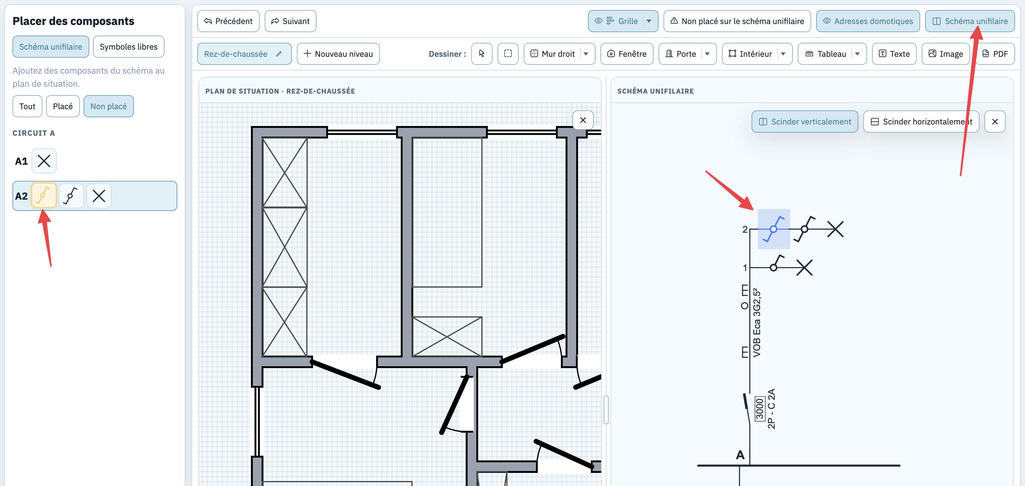
- You can also enable a split screen that shows the single-line diagram next to the layout. You can then look up the symbols that haven't been placed on the floor plan yet in the single-line diagram, and select them that way.
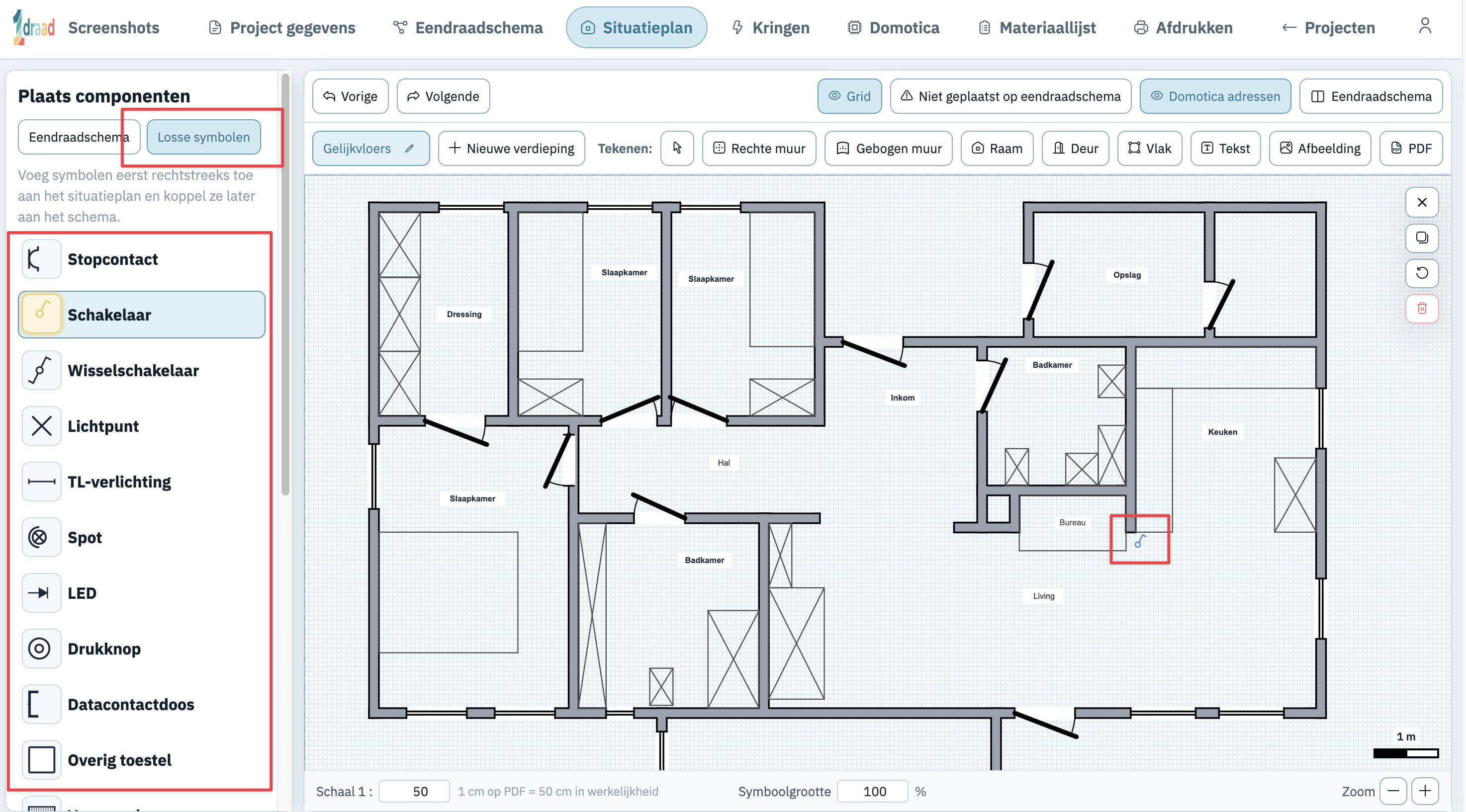
- Working the other way round is also possible: with the "free symbols" feature you can first place symbols on the floor plan and link them to the single-line diagram afterwards.
- View the automatically generated material list, set up your circuits and print the complete file as a PDF.
Way 2: Starting with the floor plan
- Start with the floor plan. Draw a layout yourself or import an existing layout from an image or PDF. 1wire can automatically clean up or convert a busy architect's plan into editable walls, windows, doors and stairs.
- Use the "free symbols" option to place the symbols you want on the floor plan with a simple click.
- You then add the symbols you placed on the floor plan to the single-line diagram later.
- You can adjust a symbol by changing its properties. The floor plan and single-line diagram always stay in sync.
- You can also enable a split screen that shows the floor plan next to the single-line diagram. You can then look up the symbols that haven't been placed on the single-line diagram yet in the floor plan, and select them that way.
- View the automatically generated material list, set up your circuits and print the complete file as a PDF.
2. Getting started
Opening 1wire
1wire is a web application — no download or installation needed. Open your browser and go to:
1wire works in modern browsers. If your browser isn't supported, the application will let you know.
Creating an account
If you don't have an account yet, click 'Register' on the sign-in page and enter your email address and password.
Sign in
You can sign in in two ways:
- with your email address and password
- with a magic link that you receive by email
For a magic link you only enter your email address. You then receive an email with a link to sign in right away.
Forgotten password
Click 'Forgot password?' on the sign-in page. Enter your email address and you'll receive an email with a link to set a new password.
Working without signing in
You can also try the editor without an account. In that mode you work in a temporary sample project. Your changes stay available temporarily and locally in your browser, but aren't saved as a full project in the cloud.
If you want to keep your work, create an account from the editor and carry on within your account.
Automatic clean-up or conversion to editable components of an imported plan is only available when you're signed in.
3. Managing projects
The project overview
After signing in you land in the project overview. Here you see all projects linked to your account.
- Click a project to open it.
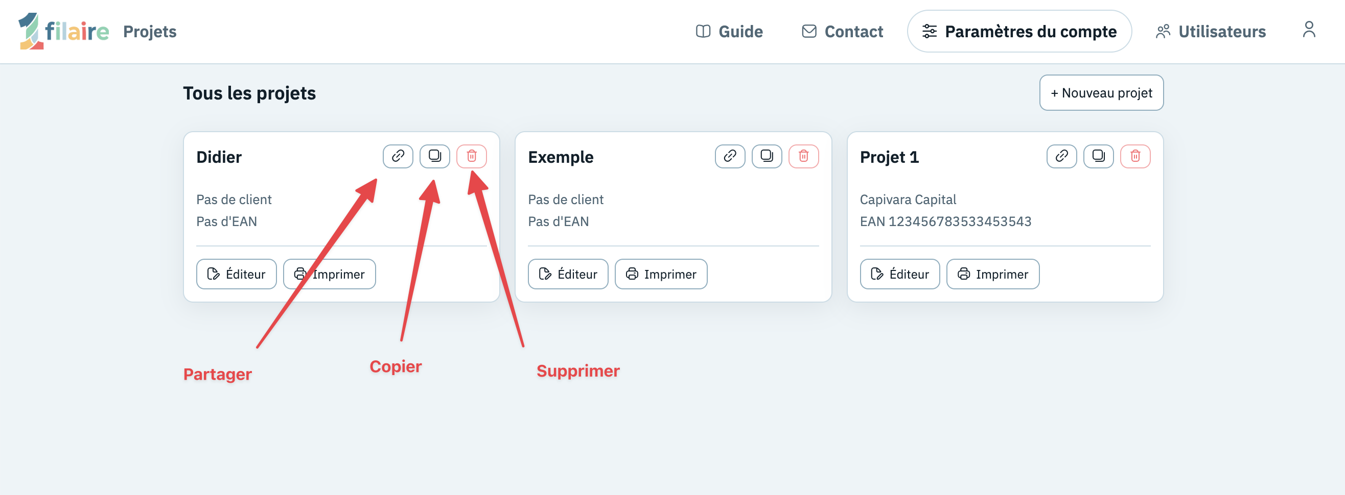
- Use the extra buttons on the project card to copy or delete a project.
- With the Edit button you open the single-line diagram directly.
- With the Print button takes you straight to that project's print page.
Creating a new project
Click the 'New project' button in the project overview. You first land on the 'Project information' form. Fill in the administrative details there and then open the single-line diagram or floor plan.
Copying a project
If you want to start from an existing file, you can duplicate a project with the copy button on the project card. The copy appears as a separate project in your overview and can then be edited independently.
Sharing a project via a public link
If you want someone to view a project without being able to change anything, you can use a public read-only link. In the project overview, click Share on the project card. You can also open the share window from Project information with the same Share.
button. When you open the share window, 1wire automatically creates a public link. You can then share it in two ways:
- Click 'Copy link' and send the link to the recipient yourself.
- Or enter the recipient's email address and click 'Send email' to send the link directly via 1wire.
The recipient can view, print and export the project via the public link, but can't change anything in your project. If the recipient has a 1wire account and signs in, they can make their own copy. Changes to that copy don't affect your original project.
Automatic saving
1wire saves your project automatically while you work. You don't have to save manually. Saving happens in the background as soon as you make a change.
Deleting a project
In the project overview you can delete a project with the delete button on the project card. A deleted project cannot be recovered.
4. Project & Administrative Details
In the 'Project information' tab you fill in the administrative information. The details of the electrical installation, installer, control organisation, installation type, current type and EAN code are used when printing the file.
At the top you also enter a project name. You'll see that name later in the project overview and at the top of the editor.
Client
Enter the client's name, address and contact details. If you like, you can also enter a company number here.
If the address of the electrical installation differs from the client's address, you can enter a different installation address.
EAN code
Optionally you can enter the EAN code of the connection. It appears on the printed documents.
1wire automatically checks whether the EAN code is a valid EAN-18 code.
Installation type, current type and installation address
In the details of the electrical installation you choose the installation type: Domestic installation or Non-domestic installation. Choose Non-domestic installation when your file needs to contain an inventory of external influences.
The External influences tab only appears for non-domestic installations. For domestic installations 1wire hides this tab; any external influences you filled in earlier are kept, but hidden and not exported as long as the project is set to domestic installation.
You also choose the current type of the connection.
If the installation address is the same as the client's address, simply tick 'Same address as client'. In that case you don't need to enter the installation address again.
Installer
- Your own details: If you are the installer yourself, your name and company details are filled in automatically from your account settings. (See Account & Settings to set up your details.)
- Another installer: If the installation is carried out by someone else, you can enter that installer's name and details manually.
Automatically completing the company number
When you enter a company number for the client, installer or control organisation, 1wire can automatically fill in empty name and address fields. Fields you filled in manually are kept.
Control organisation
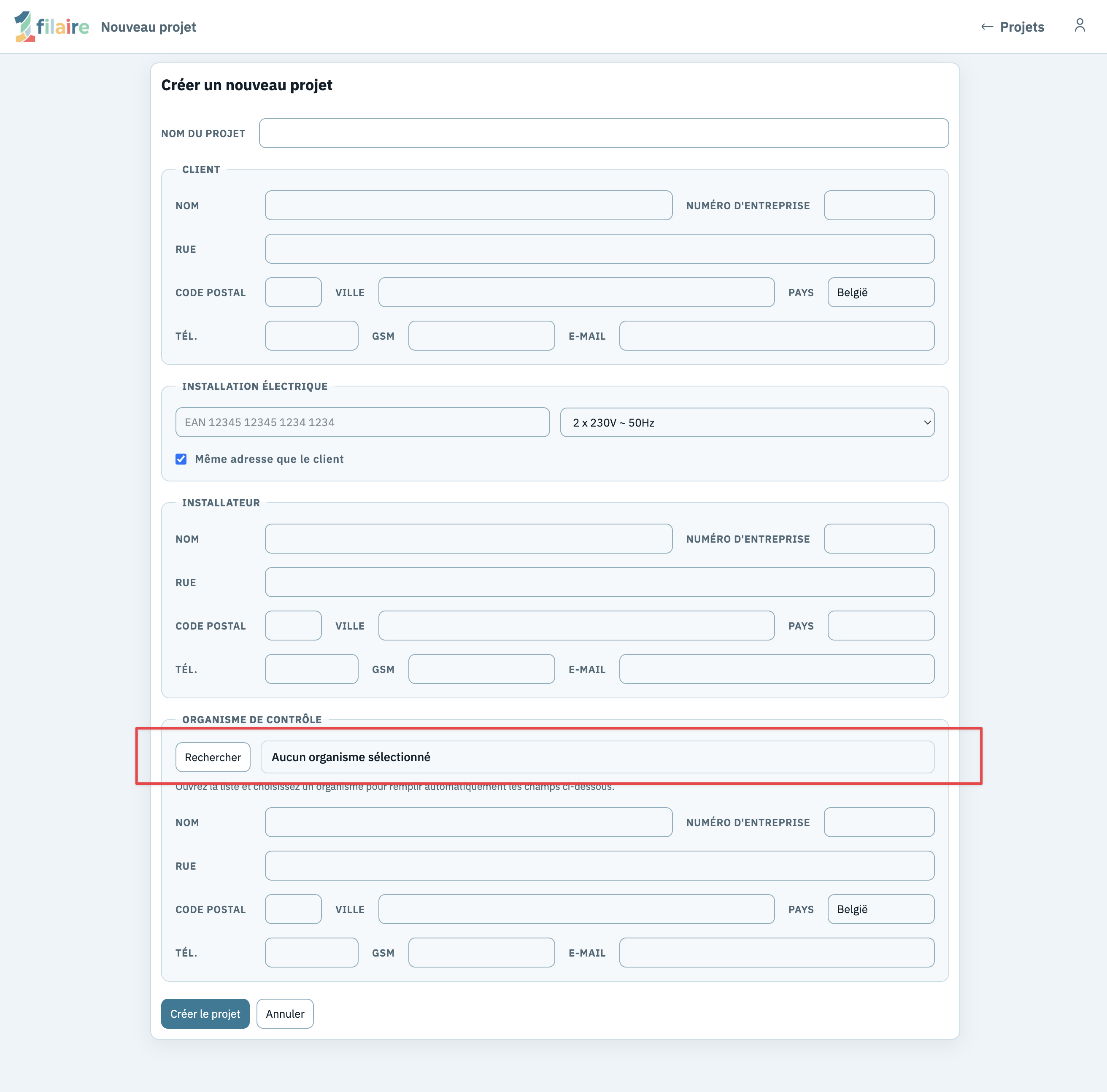
You can enter the details of the control organisation.
- Click the search icon to open a list of accredited control organisations. Select an organisation to fill in the fields automatically.
- In the list you can search by name, postcode, city or company number.
- You can also enter the details manually.
5. Single-line diagram
Click the 'Single-line diagram' tab to open the diagram editor.
Demo: open the single-line diagram
5.1 Interface overview
The screen consists of two parts:
- Left: the symbol library with all available components.
- Right: the drawing sheet on which you build the diagram.
At the top you'll find the toolbar with buttons for frequently used actions. At the bottom there are separate zoom buttons.
5.2 Toolbar

| Button | Shortcut | Function |
|---|---|---|
| Ctrl+Z (Mac: ⌘Z) | Undoes the last action | |
| Ctrl+Shift+Z (Mac: ⌘⇧Z) | Redoes the undone action | |
| — | Shows which symbols haven't been placed on the floor plan yet | |
| — | Shows or hides the circuit names on the diagram | |
| — | Shows or hides the sub-circuit names on the diagram | |
| — | Shows or hides the home automation addresses on the diagram | |
| — | Turns the split-screen view on or off |
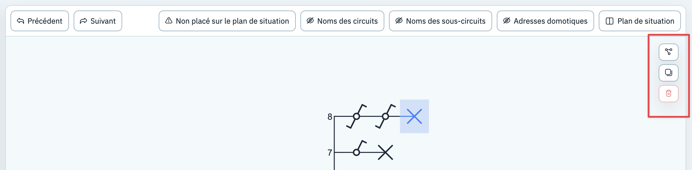
When one or more symbols are selected, additional buttons appear:
| Button | Shortcut | Function |
|---|---|---|
| S | Selects the chosen symbol together with the branch below it | |
| Ctrl+C (Mac: ⌘C) | Copies the selected symbols | |
| Delete / Backspace | Deletes the selected symbols |
5.3 Drawing the single-line diagram
Activating insert mode
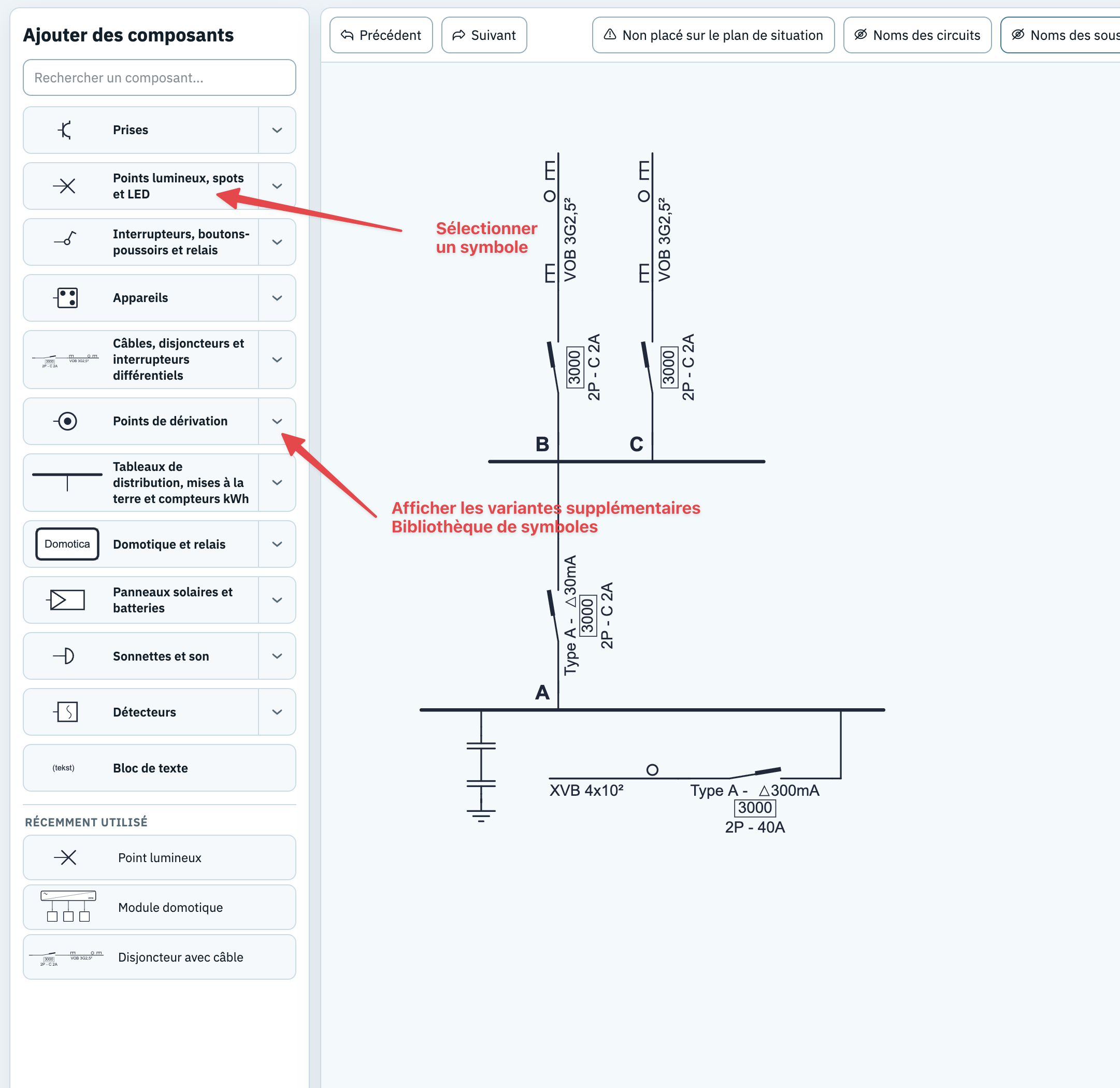
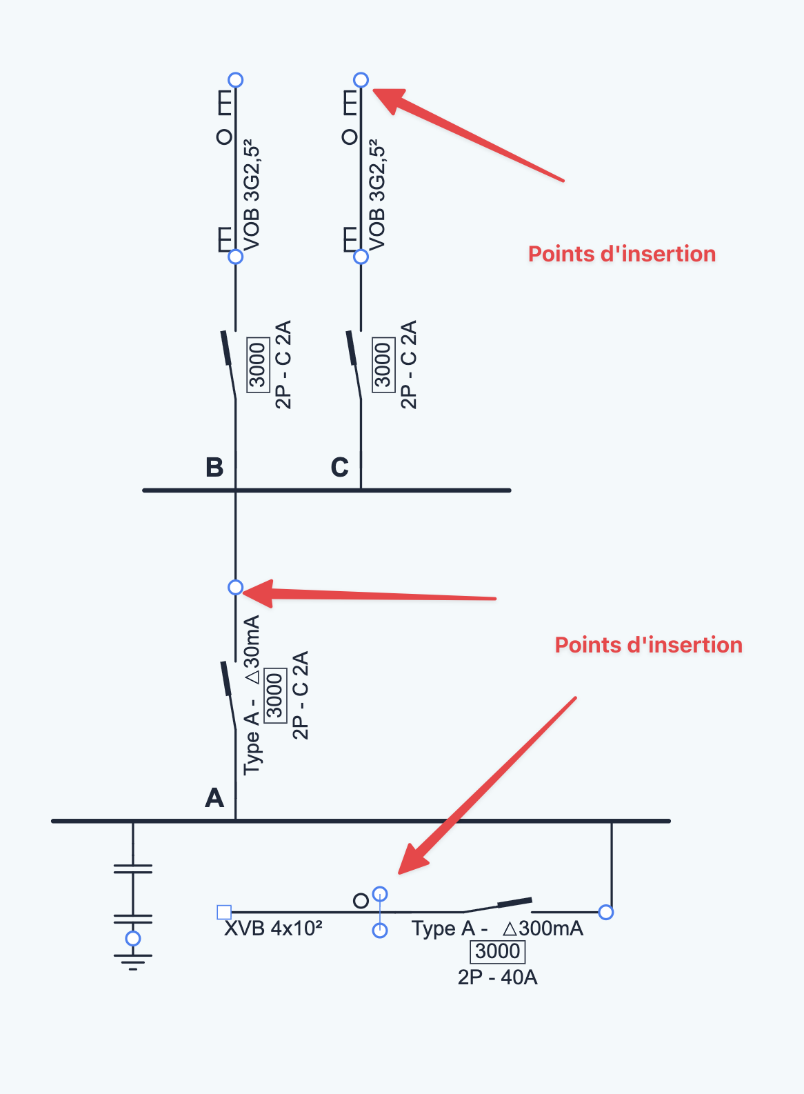
Click a symbol in the library to activate insert mode. Your cursor changes and insertion points appear on the drawing sheet. These points indicate where you can insert the symbol.
The symbol library
The library contains the available components, such as sockets, lighting, devices, cables, branch points and safety components.
Use the search field to find a component quickly. Some components have extra variants that you can open with the extra choice button.
Depending on your project, the library can also show extra lists:
- Recently used: components you added recently
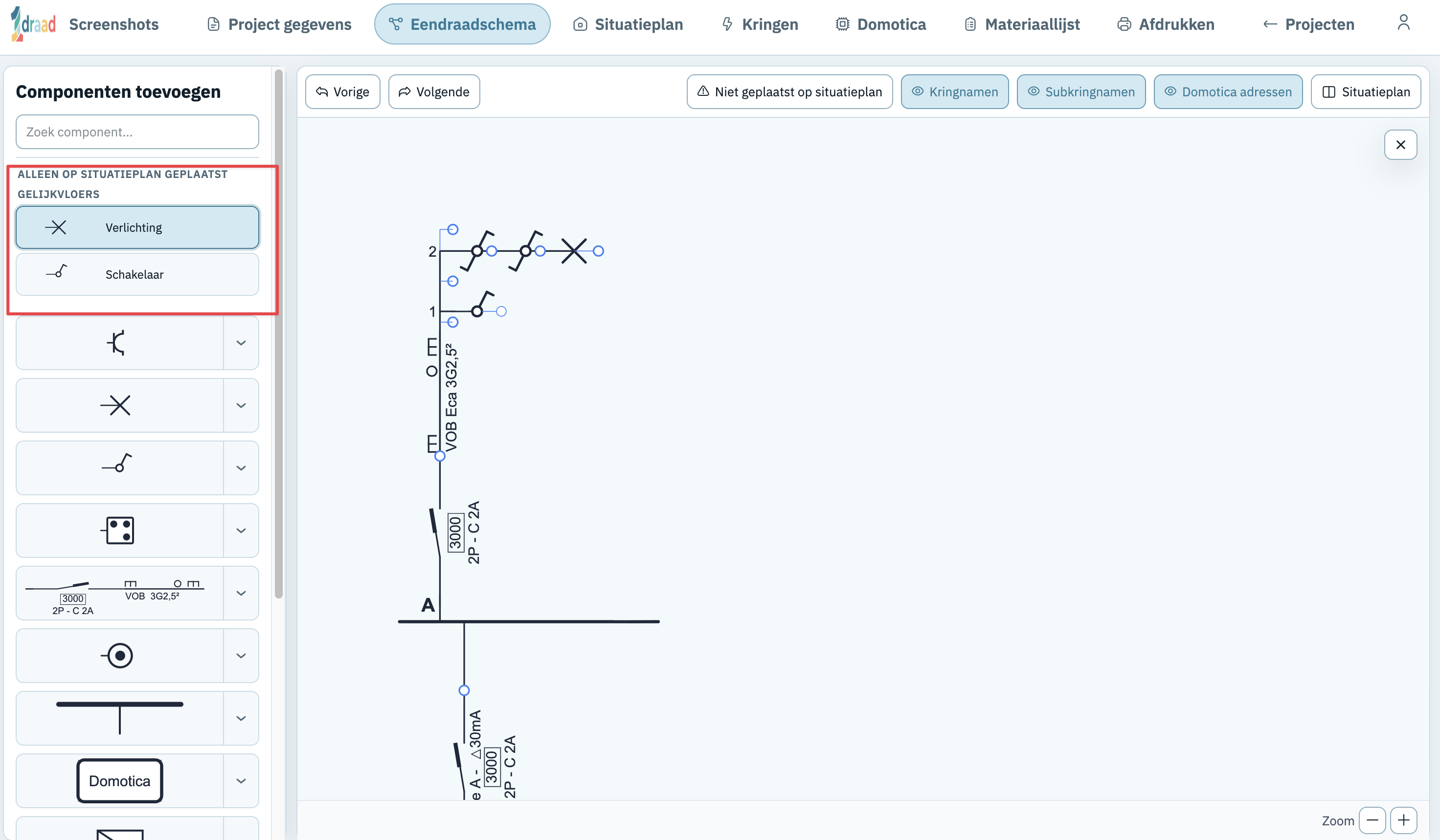
- Placed on floor plan only: free symbols that are already on the floor plan and still need to be linked to the single-line diagram
Adding a symbol
- Click the symbol you want in the library. Insert mode becomes active.
- Insertion points appear on the drawing sheet.
- Click an insertion point to insert the symbol at that position.
- Repeat step 3 to insert the same symbol in several places, or click another symbol in the library to keep drawing.
- Press Escape to leave insert mode.
Changing a symbol
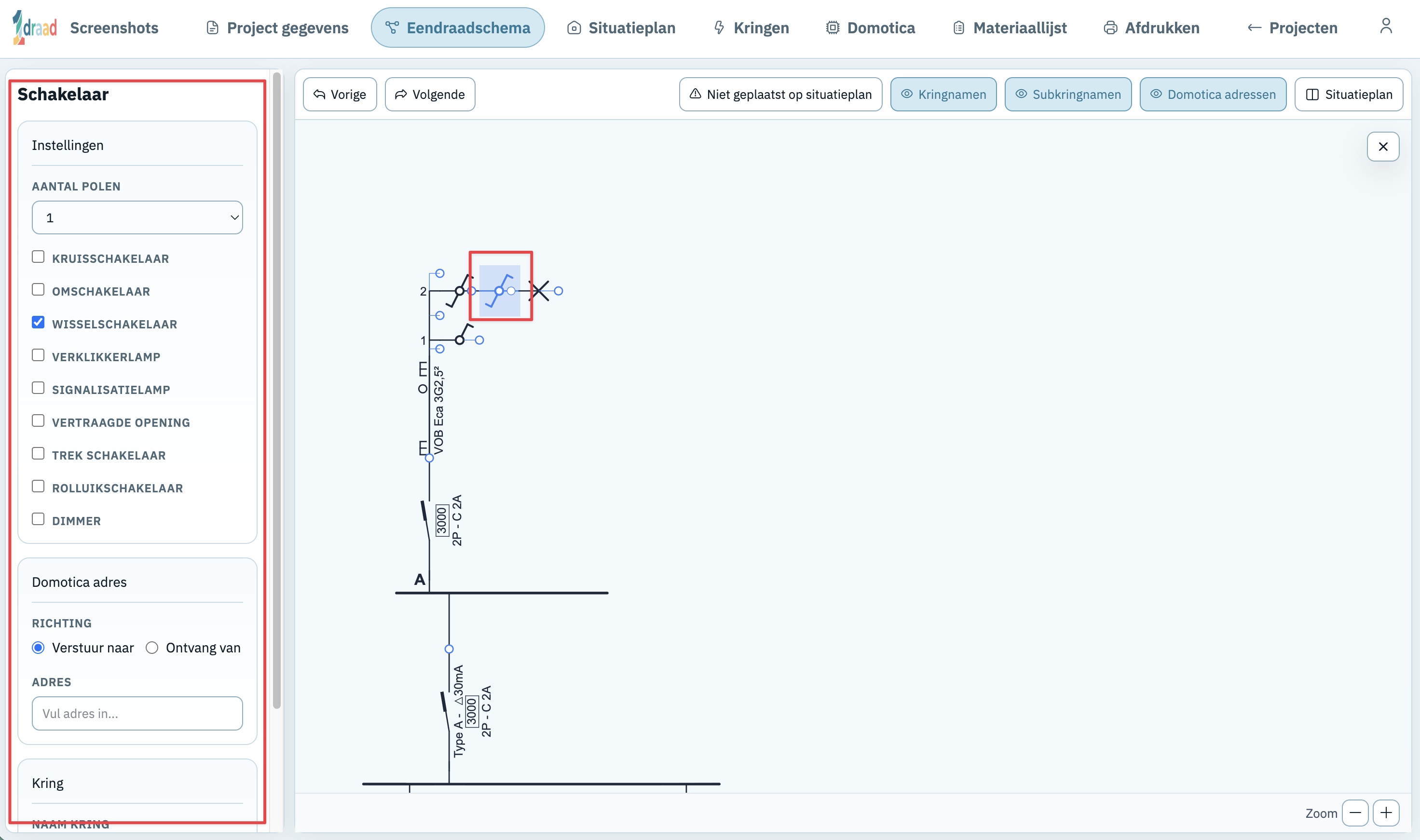
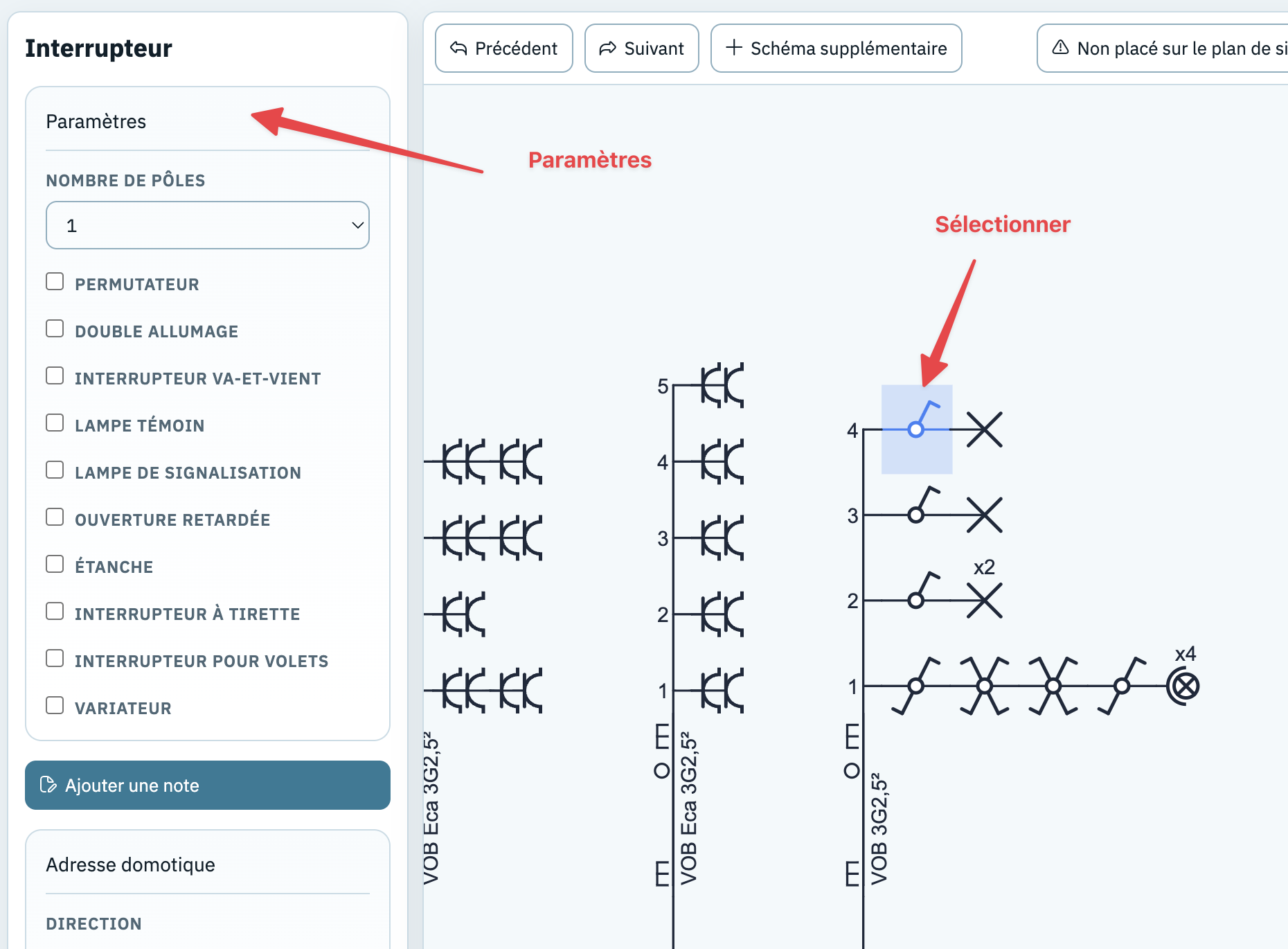
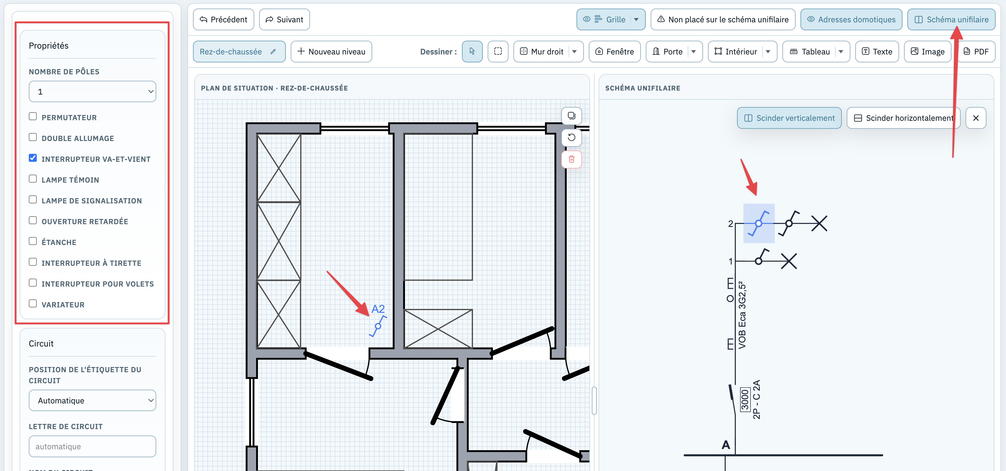
Click a symbol to select it. On the left, the properties list appears with all configurable options for that type of symbol.
Examples of properties:
- Switch: number of poles, dimmer (yes/no), roller shutter switch, pull switch, motion detector, …
- Circuit breaker: ampere rating, number of poles, cable type and cross-section
- Lamp: type (regular, fluorescent, spot, LED), dimmable
- Socket: number, waterproof, USB, child safety
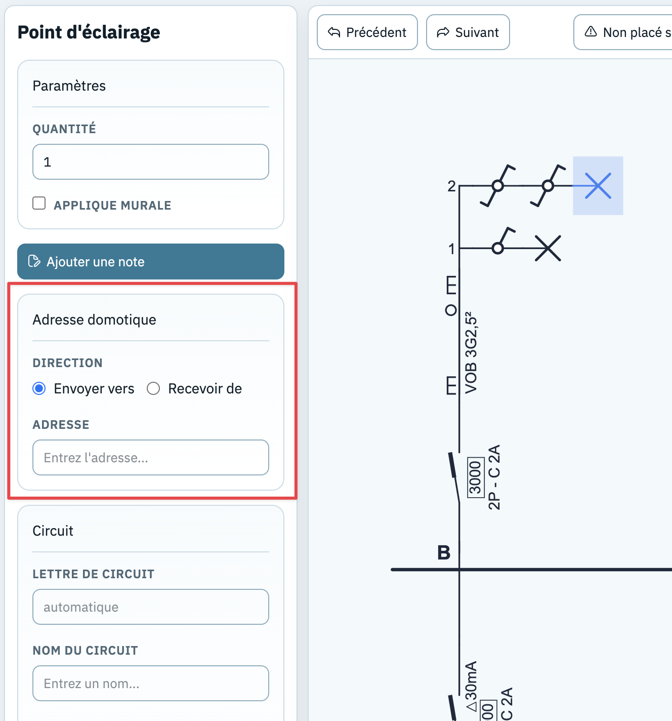
- Home automation symbol: direction of the signal and the associated address
Changes are immediately visible on the single-line diagram and on the floor plan. They are always fully synchronised.
Adding a note to a symbol
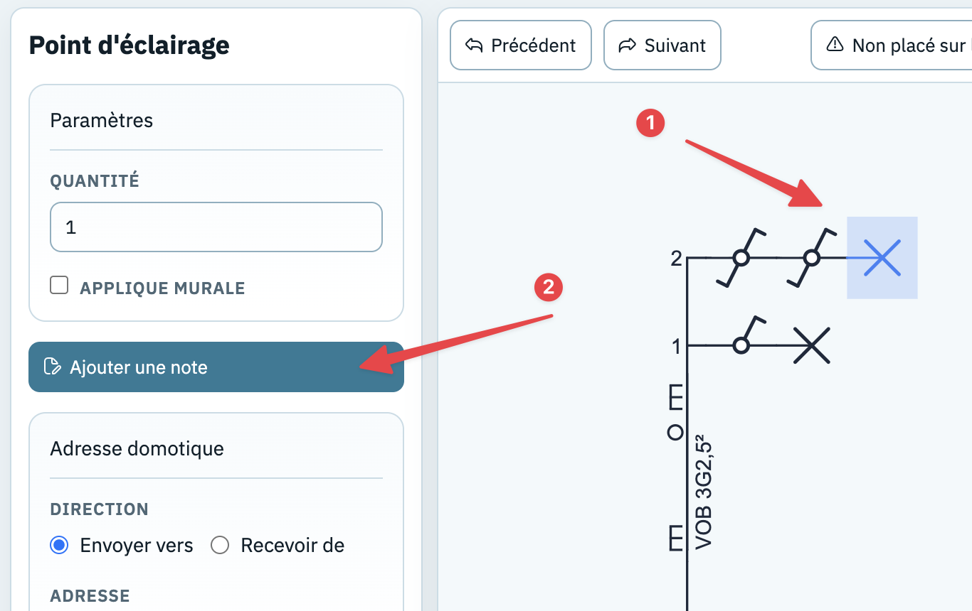
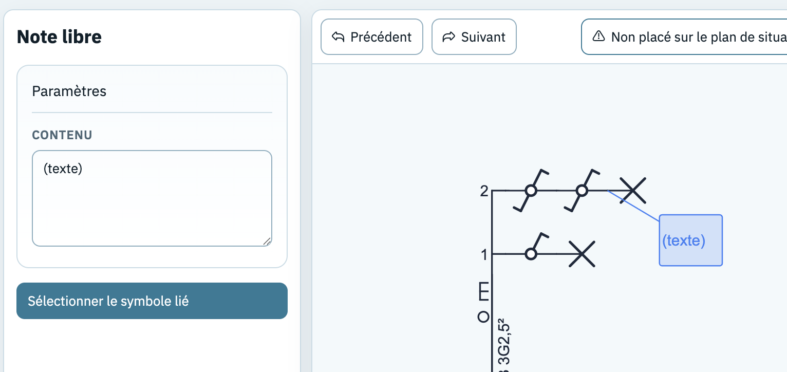
If you want to add extra explanation or a comment to a symbol, select the symbol in the single-line diagram and in the settings panel click 'Add note'. A free note appears next to the selected symbol.
The note stays linked to the symbol. You can click the note to edit the text via 'Free note' in the settings panel, or drag it to change its position around the symbol. With 'Select linked symbol' you jump from the note back to the symbol it's linked to.
Automatic numbering
Circuits and symbols are numbered fully automatically by default:
- Circuits automatically get an alphabetical label (A, B, C, …).
- Symbols on a cable automatically get a sequential number.
If you want to decide which letter a circuit gets, select a symbol on that circuit and fill in 'Circuit letter' in the circuit settings. Leave this field empty to use the automatic letter again. If the chosen letter is already used by an automatically numbered circuit, 1wire asks whether you want to swap that circuit's position.
5.4 Navigating the diagram
Zooming
- Turn the scroll wheel of the mouse over the drawing sheet.
- Use the zoom buttons at the bottom of the screen.
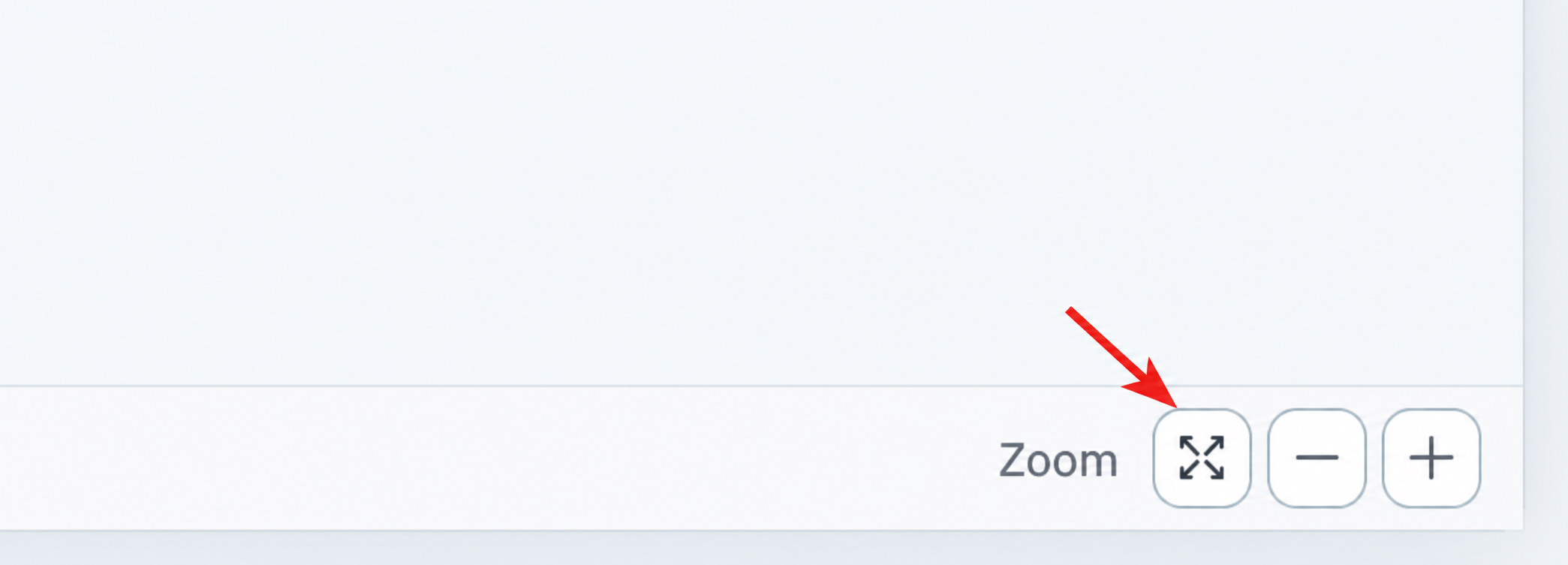
- Click Fit diagram in view (the reset zoom button with four diagonal arrows) to fit and centre the whole diagram in view again.
Moving the diagram
- Drag on the drawing sheet to move the diagram.
5.5 Selecting symbols
- A single symbol: click it in selection mode (press Escape first if you're in insert mode).
- A whole branch: select a symbol and press S to select the selected symbol together with the branch below it. Or select a symbol and click the same symbol again.
A selected symbol is marked with a blue outline.
5.6 Deleting symbols
- Select the symbol or symbols you want to delete.
- Press Delete or Backspace, or click the Delete button in the toolbar.
5.7 Rearranging symbols
- Arrow keys: rearrange the selected symbol within the tree structure of the diagram.
5.8 Copying symbols
- Select the symbols you want to copy.
- Press Ctrl+C (Mac: ⌘C) to copy, or Ctrl+X (Mac: ⌘X) to cut.
- Insertion points appear on the drawing sheet.
- Click an insertion point to insert the symbol at that position.
5.9 Circuits and sub-circuits
Each vertical line in the single-line diagram represents a circuit. Circuits are labelled alphabetically automatically (A, B, C, …).
You can override that automatic label via 'Circuit letter' in the properties list. A manually chosen letter is kept, even when other circuits are renumbered automatically. Clear the field again to let the circuit be numbered automatically.
The symbols on a circuit form sub-circuits. Each sub-circuit automatically gets a sequential number.
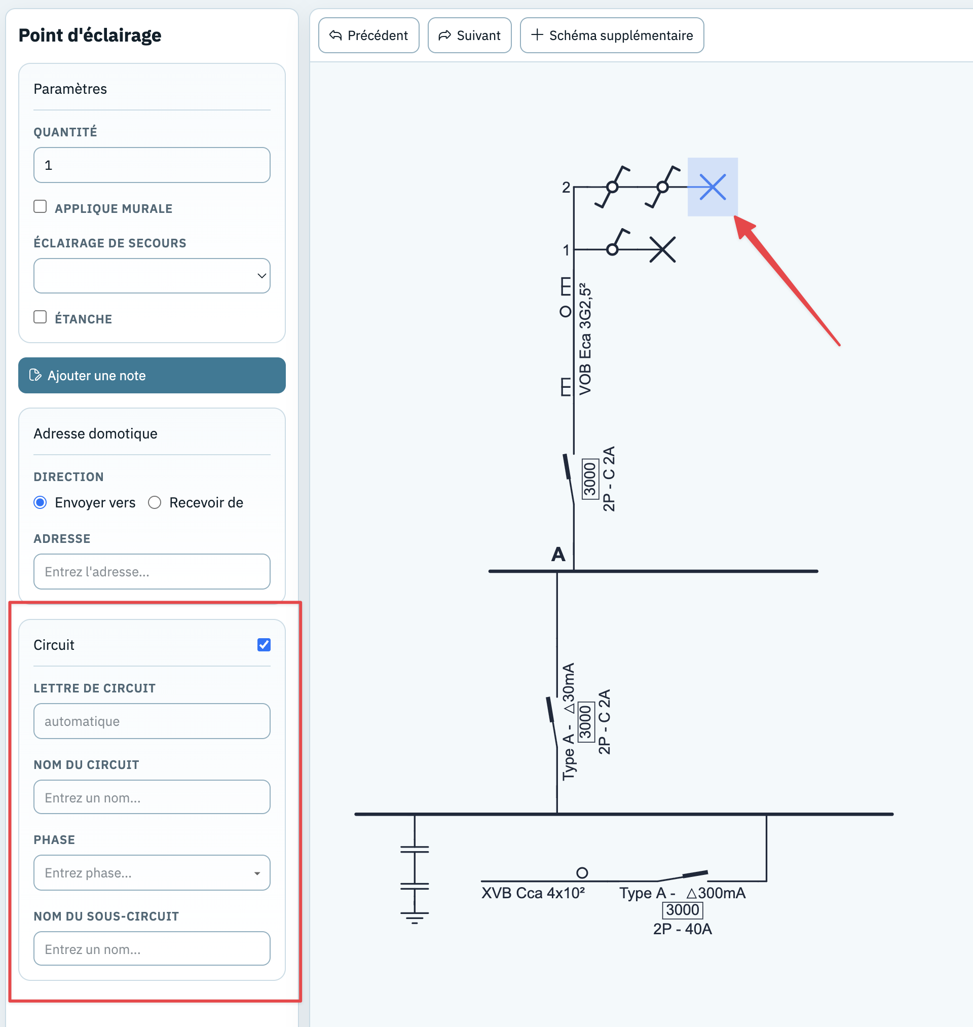
The quickest way to change a circuit name is to select a symbol on that circuit. In the properties list on the left, scroll to the 'Circuit' section and change 'Circuit name' there. With 'Sub-circuit name' you can also change the name of the associated sub-circuit in the same place. You can also manage circuit and sub-circuit names via the tab Circuits.
5.10 Home automation addresses
You can link a home automation address to every symbol. Each time you can indicate whether the symbol sends a signal to the address or receives a signal from the address. You can show or hide addresses with the toolbar button 'Domotics addresses'.
When home automation addresses are already used in your project, you'll also see them as suggestions while filling in.
5.11 Visibility options
With the toggles in the toolbar you can show or hide the following:
- Circuit names — the name of each circuit, shown above each circuit
- Sub-circuit names — the name of sub-circuits, shown next to each sub-circuit
- Domotics addresses — the addresses linked to symbols. These are typically shown below each symbol, together with an arrow that indicates whether the symbol sends a signal to the address or receives a signal from the address.

5.12 The diagram across multiple pages
If your diagram becomes too large for one page, it's automatically spread across multiple pages when printing.
You can also change the location of the page break points manually by dragging a break line with your mouse. That way you decide where a new page starts in the printout of the single-line diagram.
You can remove a manually placed break point by double-clicking it. The line is then placed automatically again.
5.13 Split-screen view
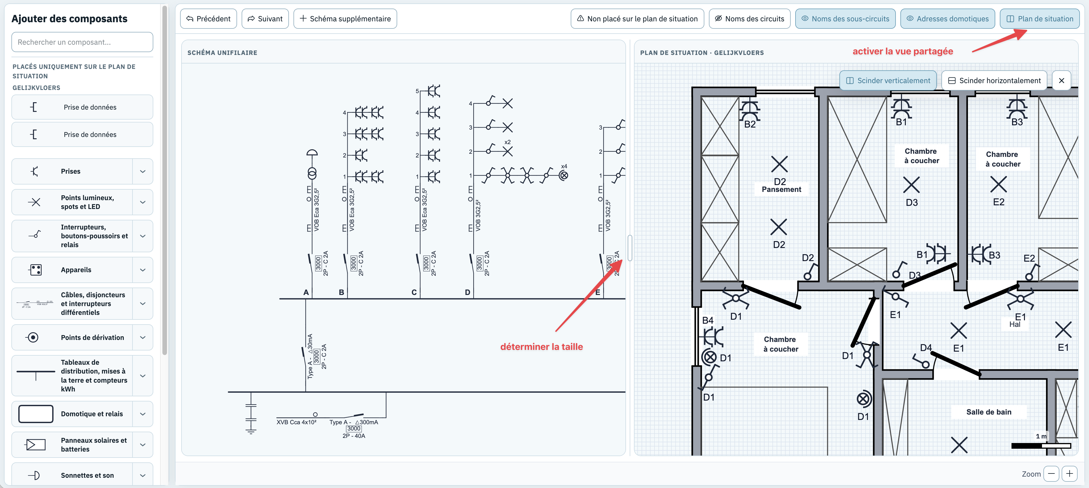
Click the 'Floor plan' button in the toolbar to split the screen. You'll then see the single-line diagram on the left and the floor plan on the right. This is handy for working on both at the same time and checking the link between diagram and plan.
A selected symbol is highlighted in both screens at the same time. If there are multiple floors, you can also switch between floors on the right in the split screen.
If there are freely placed symbols on the floor plan, you can also select them on the right in the floor plan and insert them directly on the left in the single-line diagram.
Click the button again to turn off the split-screen view.
5.14 Undoing changes
- Undo: Ctrl+Z (Mac: ⌘Z) or the "Previous" button at the top
- Redo: Ctrl+Shift+Z (Mac: ⌘⇧Z) or Ctrl+Y or the "Next" button at the top

6. Floor plan
Click the 'Floor plan' tab to open the floor plan.
6.1 Interface overview
The screen consists of two parts:
- Left: the drawing tools and the list of symbols from the single-line diagram and free symbols to place.
- Right: the drawing sheet with the layout.
At the top you'll find the floor tabs and the toolbar with drawing tools. At the bottom you can adjust scale, symbol size and zoom.
6.2 Toolbar

Drawing tools:
| Tool | Function |
|---|---|
| Select, move and edit elements | |
| Select multiple elements with a box | |
| Draw a straight wall | |
| Draw a curved wall | |
| Draw a rectangular room with four walls in one go | |
| Add a window to a wall | |
| Add a door to a wall | |
| Add a gate to a wall | |
| Add an opening without a door leaf to a wall | |
| Open the interior tools; by default you place a zone | |
| Add a reserved area or marking | |
| Draw a staircase on the floor plan | |
| Place a distribution board or other board on the floor plan | |
| Place a ground strip on the floor plan | |
| Place a grounding symbol on the floor plan | |
| Add free text | |
| Import an image or PDF as a background or convert it into editable components. See Importing a layout. |
View and workflow buttons:
| Button | Function |
|---|---|
| Shows or hides the grid. From the menu on this button you also set snapping to the grid, magnetic walls, ortho assist and the grid size. Small icons on the button show which aids are active. | |
| Makes new points and moved elements snap to the nearest grid point automatically. | |
| Makes walls, doors and windows connect automatically to existing wall axes while drawing or moving. | |
| Makes walls, windows, doors and stairs snap to 0° or 90° automatically while drawing. See Drawing straight with ortho assist. | |
| Shows components that aren't linked to the diagram yet | |
| Shows or hides home automation addresses on the plan | |
| Turns the split-screen view on or off |
Selection actions (when something is selected):
| Button | Shortcut | Function |
|---|---|---|
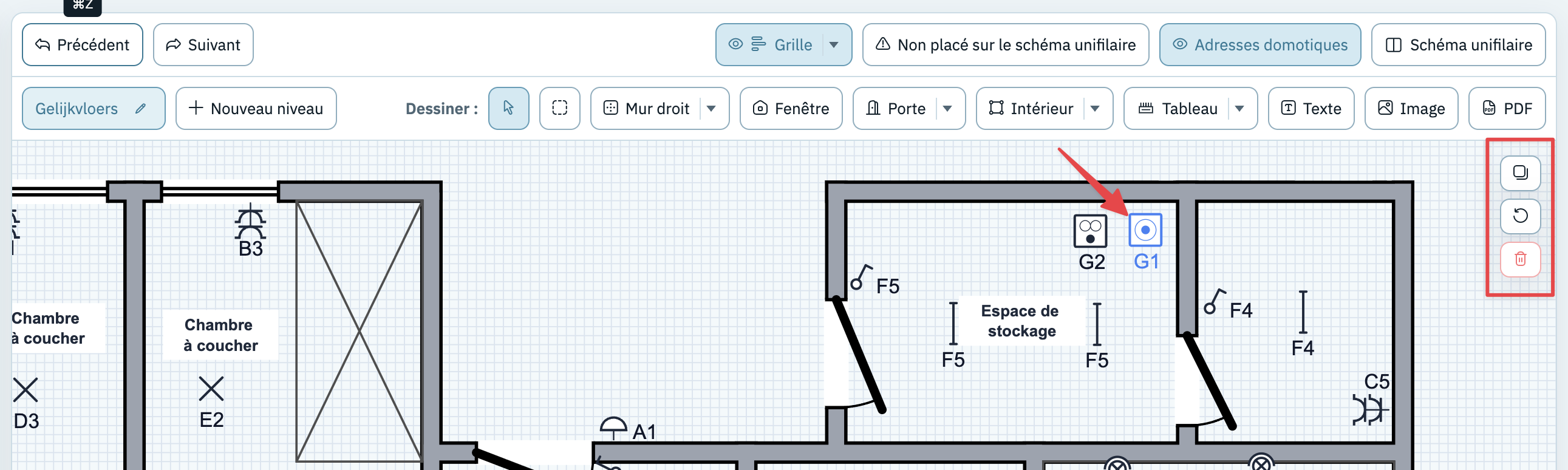
| Ctrl+C (Mac: ⌘C) | Copies the selected element | |
| R | Rotates a selected symbol or text box | |
| Delete / Backspace | Deletes the selected element |
Right-click action menu
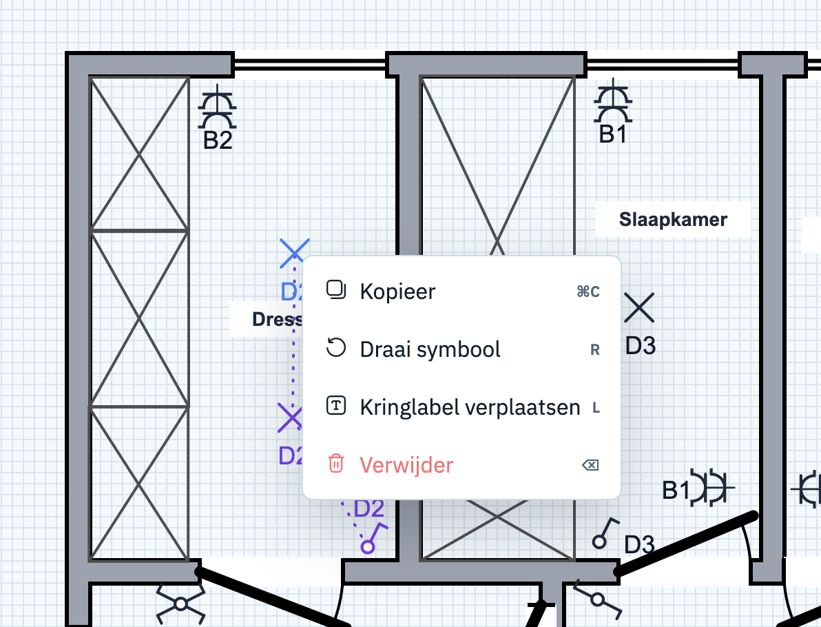
Click with the right mouse button on an element in the floor plan to open a context menu with the available actions. Depending on what you select, you can for example copy, group, ungroup, rotate, straighten an almost straight wall, lock or clean up a background image, swap door settings, or move or delete the circuit label.
If you open the menu on an element that is part of a multiple selection, the other selected elements stay selected so you can perform the action on the whole selection.
Selecting multiple elements
Use the selection tool and hold Ctrl (Mac: ⌘) while clicking elements on the floor plan. Each clicked element is added to the selection; click a selected element again with the same key to remove it from the selection. If you click without Ctrl or ⌘, you start again with one selected element.
You can combine different kinds of elements, such as walls, windows, doors, zones, text, boards, free symbols and placed electrical symbols. Drag one of the selected elements to move the whole selection together. With Escape you clear the selection.
6.3 Drawing the layout
Draw walls
- Select the tool 'Straight wall'.
- Click on the drawing sheet to place the start point of the wall.
- Move your mouse and click again to set the end point of the wall.
For a curved wall choose 'Curved wall'. You first place the start and end point and then set the curvature.
Adding doors and windows
- Select the tool 'Door' or 'Window'.
- Click on the plan to set the start point and click again to set the end point of the door or window segment.
Zones and text
Use Zone for markings such as cupboard spaces or technical zones. Use Text for free annotations on the plan.
Drawing straight with ortho assist
You almost always want walls, windows, doors and stairs perfectly horizontal or vertical. There are two ways to do this, which you can freely combine:
- Per line, with the Shift key: hold Shift while drawing. The line is then hard-locked to horizontal or vertical. Handy when you only need a perfectly straight wall now and then.
- For your whole plan, with ortho assist: turn on ortho assist. Lines then snap automatically as soon as you get close to 0° or 90°, without having to hold a key.
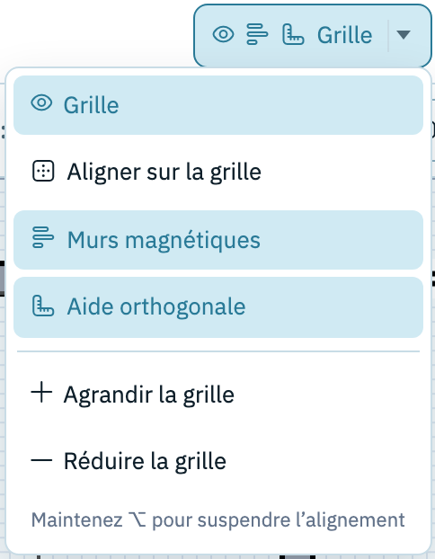
You turn on ortho assist from the menu on the 'Grid' button in the toolbar. It is off by default; as soon as it's on, a small icon appears on the grid button.
With ortho assist on, the following happens while drawing:
- If your line comes within about 5° of the horizontal or vertical axis, it snaps automatically to 0° or 90°.
- It only lets go once you clearly rotate further (about 7°), so the line doesn't keep jumping back and forth.
- The correction stays limited: a point is never moved more than about 40 cm at full scale, and never more than a small jump on screen. So a wall that really is at an angle stays at an angle.
- Next to your line you see the length and the angle while drawing, so you can immediately see whether it's straight.
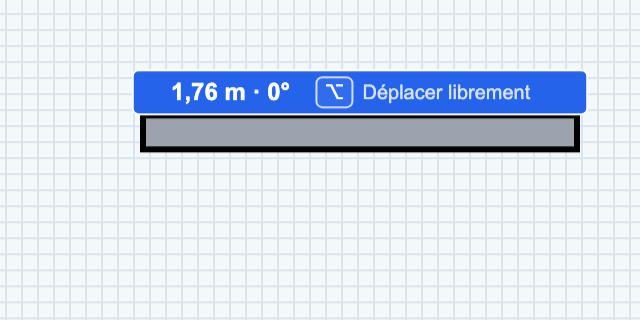
Ortho assist works both when drawing a new straight wall, window, door or staircase and when dragging an end point of an existing element. It has no effect on curved walls.
Keys while drawing and dragging:
- Shift held down locks the line hard to horizontal or vertical, whether ortho assist is on or off. The length then shows the label 'locked'.
- Alt (Mac: ⌥) held down pauses all snapping: grid, magnetic walls and ortho assist. That way you place a point exactly where you want it. Alt always takes precedence over Shift.
Straightening an almost straight wall
If a wall, window, door or staircase is just slightly off — for example traced from an imported plan — you can straighten it afterwards. Select the element with the selection tool. If it's almost straight, a small button appears below the element 'Straighten to 0°' or 'Straighten to 90°', with the current angle below it (e.g. 'Currently 4.5°'). Hover over that button to see in grey where the element will end up; click it to straighten it. You'll find the same action with the right mouse button under 'Straighten'.
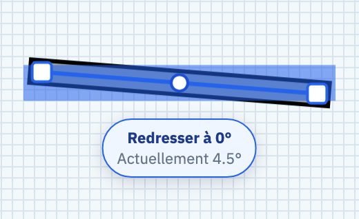
The button only appears for a deviation of up to about 7°. If a wall is clearly at an angle, 1wire assumes that's intentional.
When straightening, 1wire takes the rest of your plan into account:
- If the element connects to another element, it rotates around that connection point so the connection is kept. If it connects on both sides, the busiest node is used as the pivot. If it's free-standing, it rotates around its centre.
- Elements connected to the moved end point move along.
- Windows and doors in the wall rotate along and stay correctly in the wall.
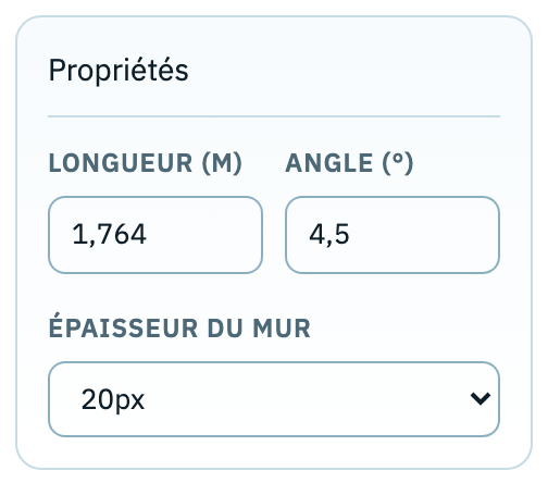
If you want an exact angle instead of 0° or 90°, fill in the field 'Angle (°)' in the settings panel on the left (see Adjusting elements).
6.4 Importing a layout
If you have an existing layout, for example a plan from the architect, you can import it as a background or have it converted into walls, windows, doors and stairs that you can then edit yourself:
- In the toolbar, click 'Image' and select an image or a PDF file. For a PDF, you indicate on the next screen which pages you want to import.
- Under 'Add image to' choose where the plan goes (see below).
- Under 'What do you want to do with this image?' choose whether you add the plan unchanged, have it converted into editable components or have it cleaned up (see below).
- Click 'Continue'.
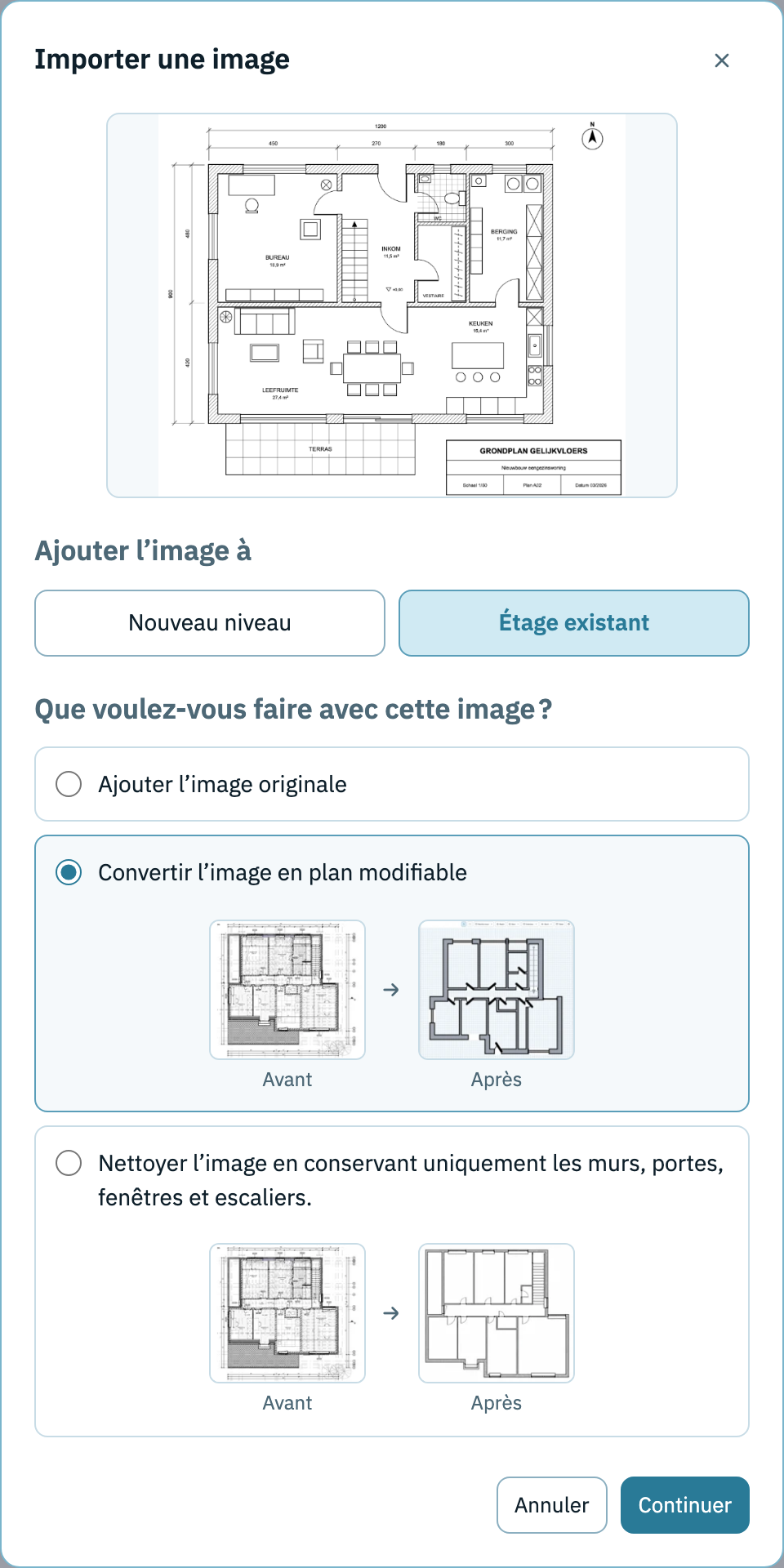
Under 'Add image to' you choose:
- Existing floor: the plan is added as an extra image on the floor you have open. For a PDF, all selected pages go on that floor.
- New floor: 1wire creates a new floor. For a PDF, each selected page becomes a separate new floor.
Under 'What do you want to do with this image?' you choose:
- Add the original image: the plan is added unchanged as a background image on the floor. This is the default choice.
- Convert the image into an editable groundplan: 1wire traces the walls, windows, doors and stairs of the plan as real elements that you can move, edit and delete. The original image stays underneath (see Converting an imported plan into editable components).
- Clean up the image, keeping only walls, doors, windows and stairs: the plan stays an image, but furniture, text, dimension lines and other details disappear (see Cleaning up an imported plan).
You can then move, scale and, if needed, delete the imported images again.
Once you're happy with the position and scale, you can lock the background. Select the image and click the padlock at the top right of the image, or use the option 'Lock location' in the settings panel. A locked image stays selectable, but can't be dragged or resized with its corner points by accident. Click the padlock again or turn off 'Lock location' to unlock the image again.
Converting an imported plan into editable components
An imported plan normally stays an image: you can place symbols on it, but you can't move a wall or adjust a door. If you have the plan converted, 1wire recognises the walls, windows, doors and stairs in the image and traces them as real floor plan elements, at the same place and scale as the image. You can then edit them like elements you drew yourself (see Adjusting elements).
You can have a plan converted in two ways:
- Right when importing: in the import window, choose 'Convert the image into an editable groundplan' before clicking 'Continue'. This works for both images and PDFs.
- Afterwards: select the imported image and in the settings panel on the left click .
Converting takes a few minutes per image. While it's in progress, the image shows 'Converting original image…'. You don't have to wait for it: feel free to close the window and keep working on the floor plan. As soon as it's done, the new components appear on your plan automatically and you also get an email.
After converting:
- the original image stays under the drawn components, so you can compare the result. If you're happy, select the image and click 'Delete' to keep only the editable walls, windows, doors and stairs;
- the converted components are grouped together, so you can move them in one go. If you want to delete or edit a single component, right-click the walls and choose 'Ungroup';
- the components are separate from the image: they don't move along if you move or scale the image afterwards. If you want to bring the plan to the right scale first, import the original image and only convert it afterwards via the settings panel.
Cleaning up an imported plan
An architect's plan is often full of furniture, dimension lines, text and other details you don't need on a floor plan. 1wire can automatically clean up such a plan: only the walls, windows, doors (with their swing direction) and stairs remain. Furniture, kitchen units, sanitary fittings, text, dimension lines, floor patterns, the title block and other details disappear, and the white background becomes transparent. That way your electrical symbols stand out much more clearly on the plan.
You can have a plan cleaned up in two ways:
- Right when importing: in the import window, choose 'Clean up the image, keeping only walls, doors, windows and stairs.' before clicking 'Continue'. This works for both images and PDFs.
- Afterwards: select the imported image and in the settings panel on the left click . You'll find the same action with the right mouse button under 'Clean up'.
Cleaning up takes about a minute per image. You don't have to wait for it: feel free to close the window and keep working on the floor plan. As soon as it's done, 1wire automatically replaces the image with the cleaned-up version, at exactly the same place, scale and rotation.
1wire always keeps the original too. When the cleaned-up version is on your plan, the button in the settings panel and in the right-click menu is called . Click it to go back to the original. With 'Clean up' you then switch straight back to the cleaned-up version, without the plan having to be processed again.
6.5 Setting the scale
For a correct floor plan it's important to set the scale correctly.
- Default scale: 1wire uses a scale of 1:50 by default.
- Custom scale: click the scale setting at the bottom of the screen and enter the scale you want (e.g. 1:100).
- Symbol size: at the bottom you can also set separately how large the symbols are shown on the plan, without changing the plan scale.
- Fit in A4 / A3: in the bar at the bottom you'll find two buttons that automatically fit the floor plan within an A4 or A3 page. The scale is then adjusted so that all walls, symbols and background images fit on the chosen page. Handy for quickly checking whether your plan can be exported correctly on one page.
6.6 Placing electrical symbols
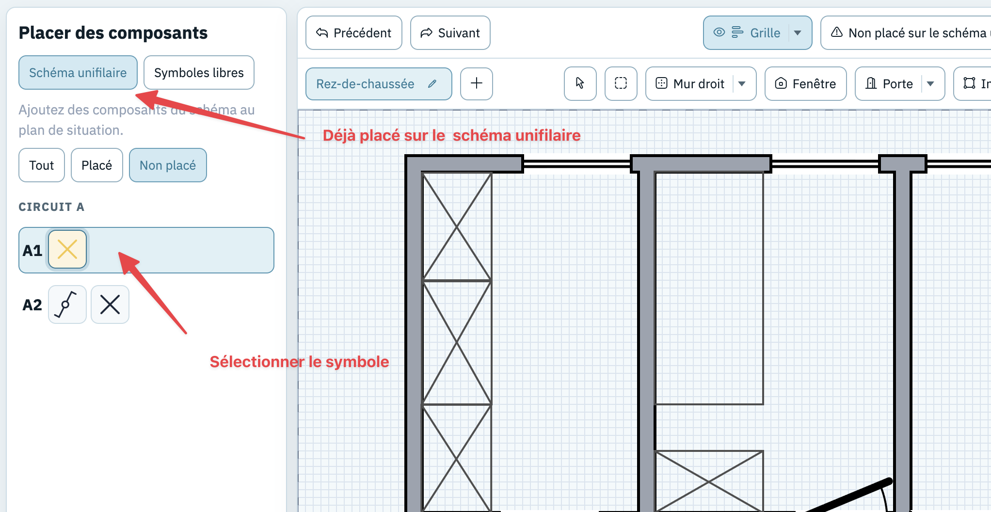
The symbols you added in the single-line diagram are available in the symbol list on the left. This is how you bring them onto the floor plan:
- Find the symbol in the list. Symbols are grouped per circuit and sub-circuit.
- Click the symbol in the list to activate placement mode.
- Click the spot you want on the layout to place the symbol there. While placing, you can also press the R key to rotate the symbol. Using the right mouse button has the same effect.
You can drag a placed symbol to another position.
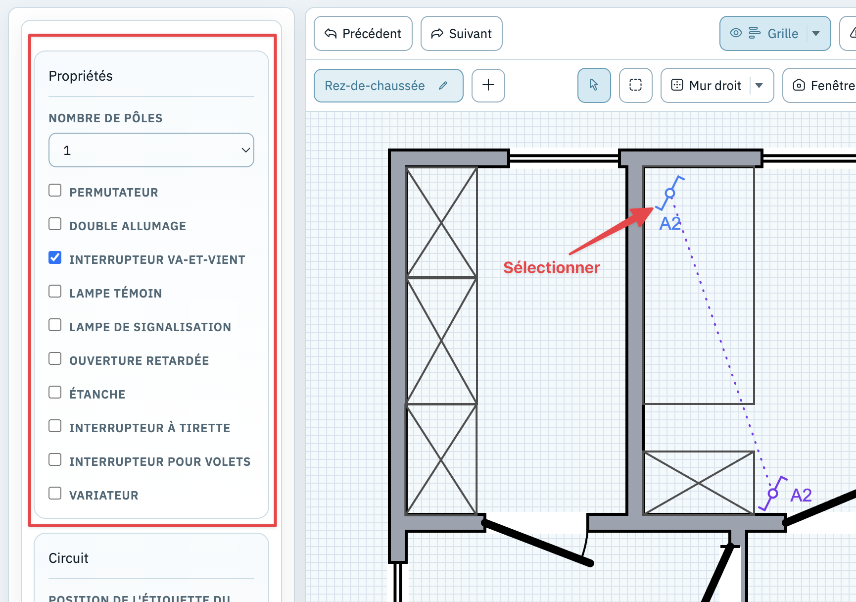
When you select a placed symbol on the floor plan or hover over it, the other symbols in the same sub-circuit light up purple.
On the left you can filter by All, Placed or Not placed. That way you quickly see which symbols are still missing from the floor plan.
To remove a symbol from the floor plan without deleting it from the single-line diagram: select it on the floor plan and press Delete.
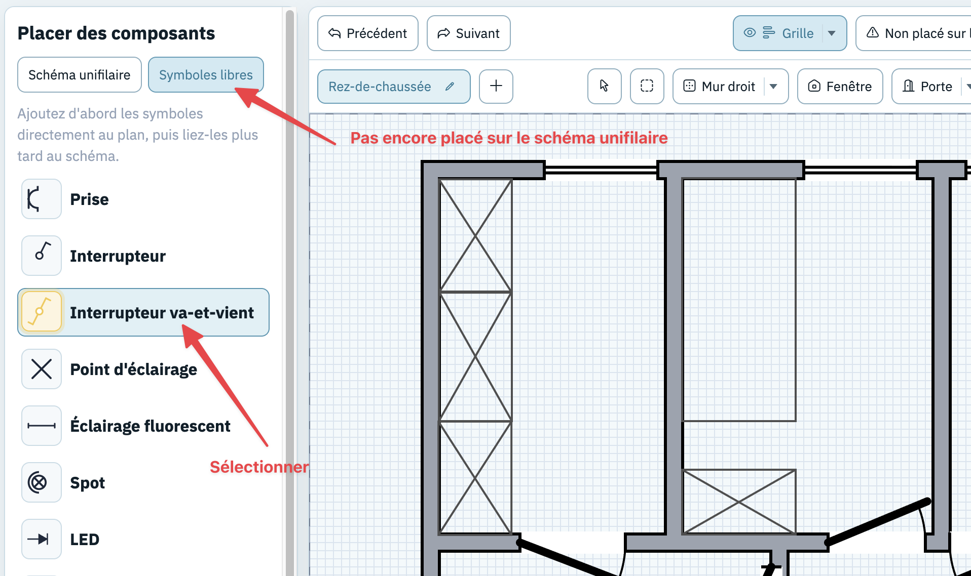
6.7 Free symbols
With free symbols you can work the other way round: you first place symbols on the floor plan and then link them to the single-line diagram.
- Select a symbol type from the library in the left column.
- Click on the floor plan to place the symbol.
- The symbol is now on the plan as a free symbol. You can then link it to a circuit in the single-line diagram.
These free symbols later appear in the single-line diagram under the list 'Placed on floor plan only', so you can easily take them over there.
6.8 Multiple floors
You can keep a separate layout for each floor.
- Click the button + New floor to add a new floor.
- Click a floor's name to navigate to it.
- Click the pencil icon next to a floor name to rename it.
- Click the × icon next to a floor name to delete the floor.
Each floor has its own background, its own layout elements and its own placed symbols.
6.9 Copy and paste
- For walls, windows, doors, placeholders and text boxes you can use Ctrl+C (Mac: ⌘C) and Ctrl+V (Mac: ⌘V) to copy and paste, also to another floor.
- For placed electrical symbols, Ctrl+C activates a new placement mode for a copy of that symbol.
6.10 Adjusting elements
When you select an element, the settings panel appears on the left. There you can, among other things:
- set the length of walls, windows and doors numerically
- set the angle of a wall, window, door or staircase numerically via the field 'Angle (°)' next to the length. The element rotates around the same pivot as with Straighten, so connected walls and the windows and doors in the wall follow along.
- change a door into a door or gate
- mirror the swing direction of a door horizontally or vertically
- give a placeholder a name, width, height and cross
- adjust a text box's text, font size, bold/italic and rotation
- scale, lock, unlock, clean up, convert into editable components or delete a background image
- adjust the position of a circuit label around a placed symbol
6.11 Display options
With the buttons at the top you can:
- show or hide the grid
- Snap to grid — turn on or off. When active, drawn points, placed symbols and moves snap to the nearest grid points. In the same grid menu you can make the grid larger or smaller.
- Magnetic walls — turn on or off. When active, walls, windows and doors automatically connect to existing horizontal or vertical wall axes while drawing or moving. This option is on by default.
- turn Ortho assist on or off. When active, walls, windows, doors and stairs snap to 0° or 90° automatically as soon as you get close enough. This option is off by default. See Drawing straight with ortho assist.
- Home automation addresses on the plan — show or hide
- mark components that don't appear on the single-line diagram yet
6.12 Split-screen view
Click the button 'Single-line diagram' button to show the floor plan and the single-line diagram side by side.
In this view selections stay linked: choose a symbol on the plan and you immediately see where it belongs in the single-line diagram, and vice versa.
What's more, you can select an unplaced symbol in the single-line diagram and place it directly on the floor plan
7. Circuits
Click the 'Circuits' tab for an overview of all circuits and sub-circuits of the project.
Overview
The circuits page shows a hierarchical list:
- Circuits — the vertical lines in the single-line diagram, labelled with a letter (e.g. circuit A, circuit B, …)
- Sub-circuits — the numbered branches within a circuit, labelled with a number after the circuit letter (e.g. A1, A2, B1, …)
How circuits are created
You don't create circuits on the circuits page. Circuits and sub-circuits are created automatically when you add components to the single-line diagram and assign a circuit or sub-circuit label. The circuits page automatically shows all circuits present in the diagram that way.
Renaming a circuit
The quickest way is to select a symbol on the circuit you want in the single-line diagram. In the properties list on the left, scroll to the section 'Circuit' and at the bottom change the field 'Circuit name'.
You can also rename a circuit via the tab 'Circuits': click the name of the circuit there and enter a new name (e.g. "Living room lighting" or "Kitchen sockets"). The new name appears on the single-line diagram and on all printed documents.
Every circuit and every sub-circuit can have its own name. The label (e.g. "A1") and the name are independent: the label determines the order and structure, the name describes the function.
Setting a circuit letter manually
If you want to give a circuit a fixed letter, select a symbol on that circuit in the single-line diagram or floor plan and fill in 'Circuit letter' in the circuit settings. The circuits page marks such a circuit with 'Manual'.
Clear the field 'Circuit letter' to return to the automatic label. If you choose a letter that is already in use automatically, 1wire can suggest swapping the positions of both circuits.
Renaming a sub-circuit
Click the name of a sub-circuit to edit it. By default, sub-circuits get the label of the parent circuit with a number (e.g. A1, A2). You can give each sub-circuit its own descriptive name.
Expanding and collapsing circuits
Click the arrow next to a circuit to show or hide its sub-circuits. This makes the overview clearer for projects with many sub-circuits.
8. Material list
Click the 'Material list' tab to view an automatically generated overview of all materials in the project.
How the list works
The material list is compiled automatically from the symbols in the single-line diagram. You don't have to enter anything manually. The list is updated as soon as you make changes to the diagram.
Identical components are automatically merged: two identical fuses of the same type and value appear as one row with quantity 2, not as two separate rows. Two components are considered identical if they have the same type and the same configured properties — the circuit label plays no part in this. So a component in circuit A and an identical component in circuit C are merged.
For each row in the list you see:
- The visual symbol of the component
- The quantity (e.g. "3×")
- The name of the component
- The specifications: the relevant properties such as cable type, ampere rating, power, … (only the properties that make sense for the material list are shown)
The list is sorted by name and specifications, so similar components are grouped together.
Adjusting the quantity
For most components the quantity is counted automatically based on how many times the symbol appears in the diagram. For some components you can override the quantity manually via the properties list in the single-line diagram.
Use
You can print the material list or export it as a PDF via the Print page. The PDF shows the list in a two-column layout with symbol, quantity, name and specifications per component.
9. External influences
The 'External influences' tab contains the inventory of external influence factors for the file. This page is meant for non-domestic installations where the special conditions of rooms or zones must be recorded explicitly.
9.1 When is this tab visible?
The tab only appears when in Project information the Installation type option Non-domestic installation is selected. For a domestic installation 1wire hides the tab, because the AREI works with fixed standard values for ordinary homes.
9.2 Filling in the inventory
You add a row per place or room. 1wire distinguishes between publicly accessible and non-publicly accessible places.
- First fill in the place or room, for example workshop, kitchen or technical room.
- Then choose only the external influences that apply. The columns are grouped by Environment, Use and Construction.
- Leave an influence empty when no special factor needs to be reported.
9.3 Exporting
On the Print page you can include the inventory sheet in the PDF file. This option is only available for projects set as Non-domestic installation.
10. Home automation
Click the 'Domotics' tab for an overview of all home automation addresses in the project.
Demo: open the home automation page
Overview
The home automation page shows a table of all home automation addresses used in the project. For each address you see which symbols send signals to that address and which symbols receive signals from that address.
So for each address you see a clear distinction between:
- Input address: symbols that send signals to that address (e.g. a motion detector or push button that sends a signal)
- Output address: symbols that receive signals from that address (e.g. a lamp or relay that is controlled)
For each symbol in the table you see the visual symbol, the name and the circuit label it belongs to. The rows are sorted by address.
Assigning addresses
You assign addresses to individual symbols via the properties list in the single-line diagram or the floor plan (see Domotics addresses). An address is a free text field — you type the address in the format your home automation system expects.
While filling in, the existing addresses from the project appear as suggestions, so you can easily link the same address to multiple symbols.
Exporting
You can print the home automation overview or export it as a PDF via the Print page.
11. Printing & Exporting
Click the 'Print' tab to open the print screen.
What can you print or export?
| Document | Content |
|---|---|
| Single-line diagram | The complete diagram, spread over several pages |
| Floor plan | The layout with placed symbols, per floor |
| Circuit list | An overview of all circuits and sub-circuits |
| Home automation overview | A list of all home automation addresses used |
| Material list | The overview of all required materials |
| External influences | The inventory sheet with external influence factors, only for non-domestic installations |
Choosing paper size and content
On the print page you first choose the paper size:
- A4
- A3
Then you choose which parts go into the PDF. You can select everything at once, or include only certain parts.
Extra options are available for some parts:
- for the single-line diagram: print circuit names, sub-circuit names and home automation addresses
- for the floor plan: print home automation addresses and use the option 'Scale the floor plan down so it fully fits on A4' to automatically scale the floor plan page down so it fits entirely on an A4 page
- for the circuit list: include sub-circuit names
- for the external influences: include the inventory sheet, only when the project is set as a non-domestic installation
Generating the PDF
Click the documents you want and click 'Export PDF'. Your browser downloads the PDF file.
When you include the floor plan, each floor is processed as a separate page in the PDF.
At the bottom, every page of the PDF contains the administrative details of the electrical installation, the installer and the control organisation, together with metadata such as the current type, the EAN code, the version and the page number.
12. Account & Settings
Account menu
Click the user icon at the top right to open the account menu. There you see the email address you're signed in with and you can sign out.
Account settings
On the Account settings page you can manage your language and your installer details. You open this page from the project overview via the link Account settings.
Among other things, you can manage the following details there:
- name
- address
- company number
- phone and mobile number
- email address
These details are filled in automatically as installer details for new projects and used on the printed pages.
Adding extra users
If you want to give colleagues access to the same projects, you can add extra users to your account. From the project overview, open the link Users. There you see which users are already linked and which invitations are still pending.
- Click 'Invite user'.
- Enter the new user's email address.
- Click 'Send invitation'.
The new user receives an email with an invitation link. Through that link they choose a password and then get access to the same account, including the projects linked to that account.
If someone hasn't activated the invitation yet, you can send it again from the page Users with 'Invite again'.
Log out
Click 'Log out' in the account menu at the top right.
13. Keyboard shortcuts overview
General
| Shortcut | Function |
|---|---|
| Ctrl+Z / ⌘Z | Undo |
| Ctrl+Shift+Z / ⌘⇧Z | Redo |
| Ctrl+Y / ⌘Y | Redo (alternative) |
Single-line diagram
| Shortcut | Function |
|---|---|
| Ctrl+C / ⌘C | Copy |
| Ctrl+X / ⌘X | Cut |
| Delete / Backspace | Delete selected symbols |
| Escape | Cancel insert mode / deselect |
| S | Select the selected branch |
| Arrow keys | Rearrange the selected symbol within the diagram |
| Scroll wheel | Zoom in / zoom out |
| Drag on the drawing sheet | Move the drawing sheet (pan) |
Floor plan
| Shortcut | Function |
|---|---|
| Ctrl+C / ⌘C | Copy; for placed electrical symbols this starts a new placement mode for a copy |
| Ctrl+V / ⌘V | Paste for walls, windows, doors, placeholders and text boxes |
| Ctrl / ⌘ + click | Add an element to or remove it from a multiple selection |
| Right mouse button | Open the context menu with actions for the selected element or the selection |
| Delete / Backspace | Delete selected element |
| Escape | Cancel insert mode / deselect |
| R | Rotate the selected symbol or text box |
| Shift (hold) | Lock a wall, window, door or staircase to horizontal or vertical while drawing or dragging |
| Alt / ⌥ (hold) | Pause snapping (grid, magnetic walls and ortho assist) |
| Scroll wheel | Zoom in / zoom out |
| Drag on the drawing sheet | Move the drawing sheet (pan) |
14. Drawing a backup power circuit
Installations with a home battery or an inverter with a separate backup output need a few extra elements on the diagram: the transfer module (ATS) on the distribution board, the backup connection to the inverter, and the backup power circuits that stay powered during a grid outage.
The symbols
- Hybrid inverter — the inverter with two outputs: a regular output and a backup output. The regular AC/DC symbol has only one and therefore can't get a backup connection. Searching for inverter, back-up or EPS also gets you there.
- Transfer module (ATS) — the distribution board that disconnects from the grid and switches over during a grid outage. In the symbol library you can also find it with the search terms ATS, transfer module and backup box.
- EPS system — places the whole chain on the diagram in one go: the board with the transfer module, the protective devices, the cables and the hybrid inverter, all connected to each other.
Connecting and disconnecting
Select the hybrid inverter or the board. 1wire then draws a dotted line to the open end with a button next to it. On the inverter that button is called 'Connect to transfer module (ATS)', on the board 'Connect to AC/DC'. One click makes the connection.
You disconnect in the settings panel of the connected symbol, with the button 'Disconnect transfer module (ATS)'.
Board settings
You turn a regular distribution board into a transfer module with the option 'With transfer module (ATS)' in the settings panel. With 'Transfer module (ATS) label' you change the label; by default it says Transfer switch. Everything you place on the rail behind the module is a backup power circuit.
In the separate drawing guide How to draw a single-line diagram with a backup power circuit you'll find the principle diagram, a checklist of what should be on the diagram, the complete step-by-step plan with screenshots and the mistakes that come up again at the inspection.