The inverter
The device itself, with its type and power, and with a clearly visible separate backup output next to the regular output.
More and more installations get a home battery or an inverter with a backup output. On this page you'll read step by step how to draw that backup power circuit correctly in your single-line diagram: the transfer module (ATS) on the distribution board, the hybrid inverter with its backup output, and the circuits that stay powered during a grid outage.
Drawing backup power without detours
A backup power circuit, also called an emergency circuit, is a circuit that keeps working when the public grid fails. The energy then doesn't come from the grid operator, but from a hybrid inverter, usually fed by a home battery and solar panels.
The switching itself happens in a transfer module (ATS) — until recently called the backup box. That device disconnects the installation from the grid and switches over to the inverter's backup output. On the single-line diagram you draw that module on the distribution board, where the supply enters the board. Everything behind the module stays powered during a grid outage.
For the inspection this is not a detail. Anyone reading the diagram must be able to see where the second energy source is, how it is protected and which circuits are behind it. A battery drawn only as a device in a corner doesn't tell that story.
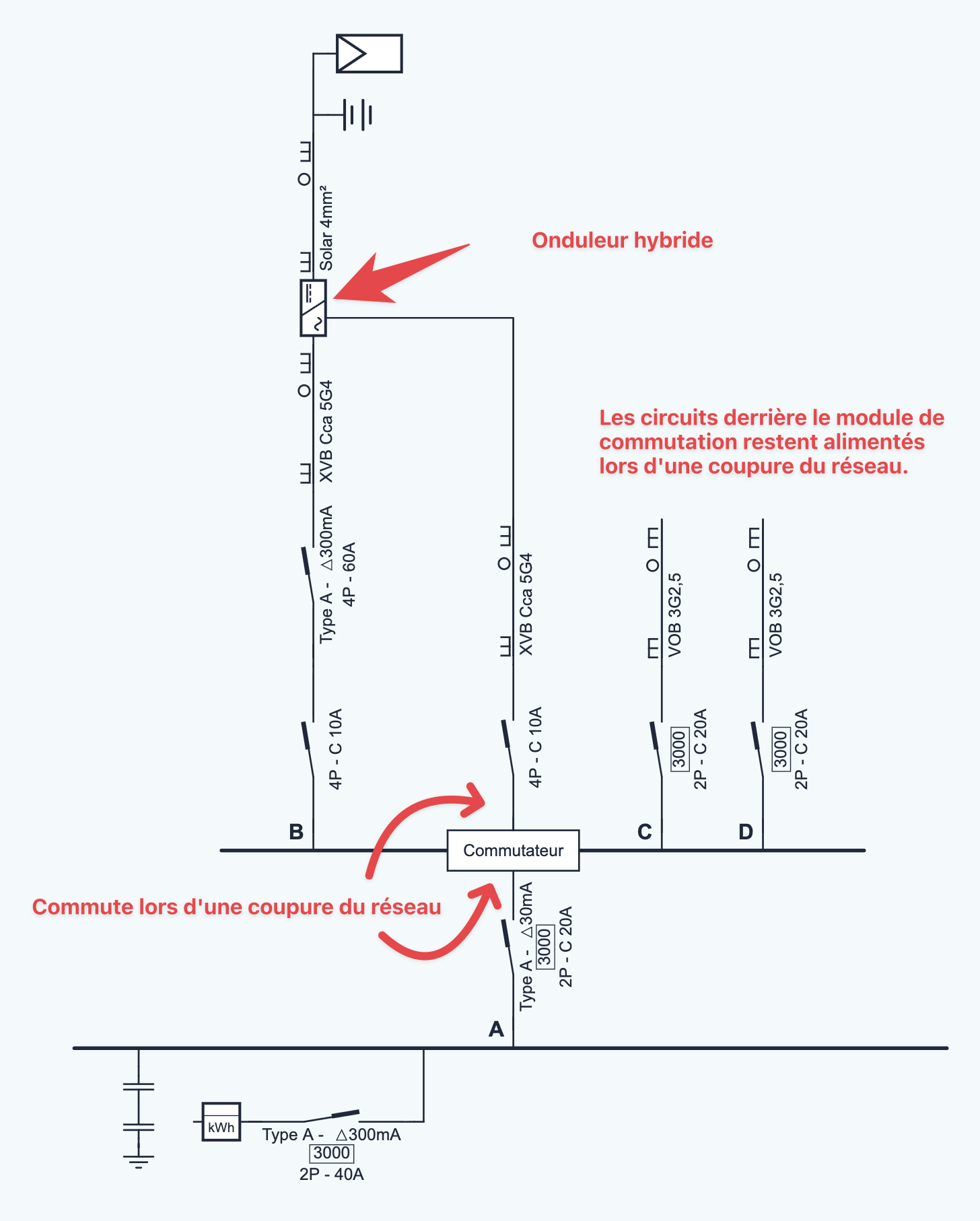
The supply of the board, from the main board. It enters at the transfer module: that is the point where switching happens during a grid outage.
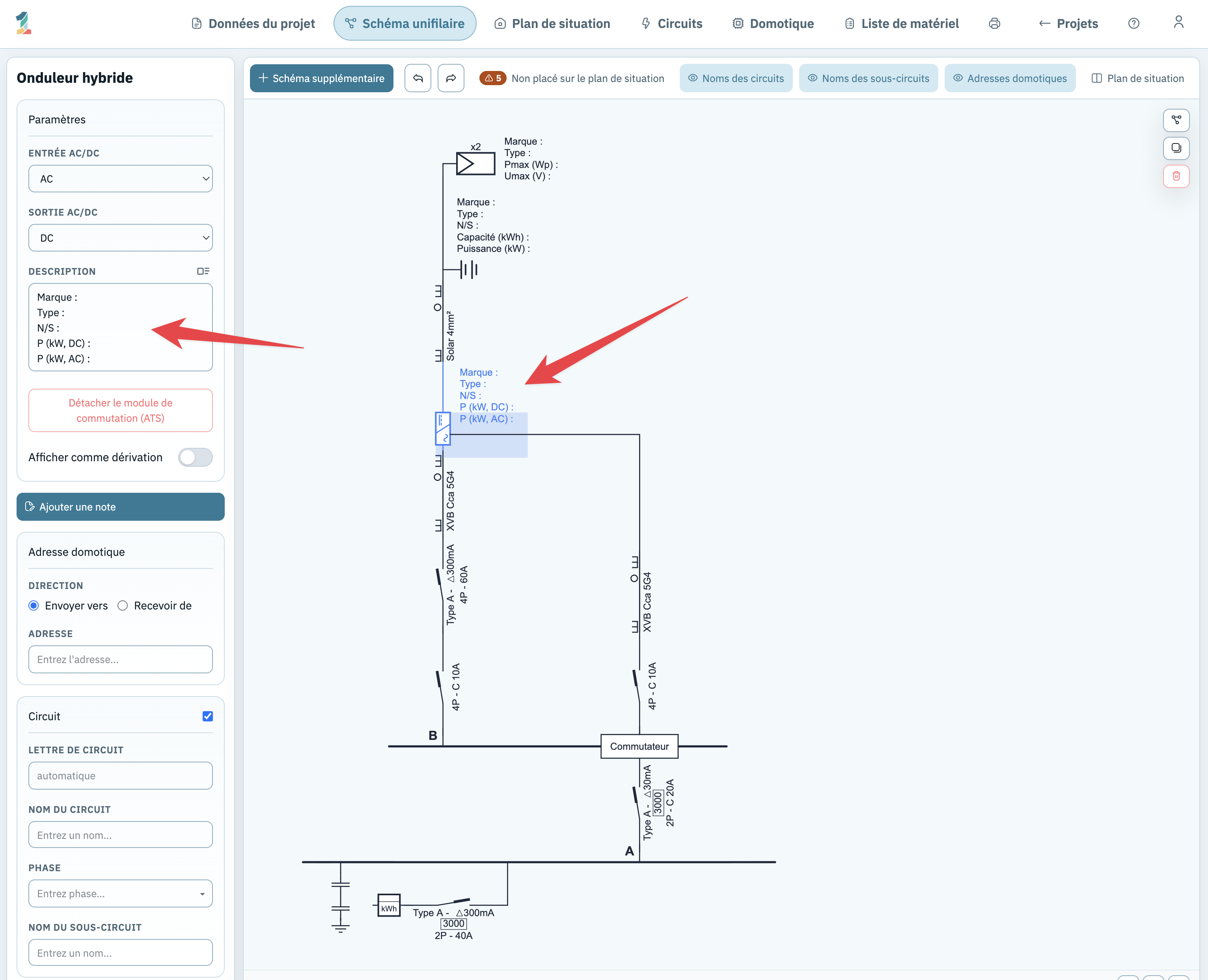
The hybrid inverter, with its circuit breaker, RCD and cable — and on the DC side the solar panels and the battery.
The backup connection: from the transfer module to the inverter's backup output, with its own circuit breaker and cable.
The circuits you put on backup power, each with its own circuit breaker and cable. You decide how many go on this rail.
The device itself, with its type and power, and with a clearly visible separate backup output next to the regular output.
The circuit breaker and the RCD the inverter is connected to, with their ratings.
Drawn on the distribution board, where the supply enters. That makes it immediately clear what is behind it.
The cable between the inverter's backup output and the module, with its own protection, cross-section and number of conductors.
Which circuits are on backup power, each with its circuit number, so the diagram and the floor plan tell the same story.
The DC side of the installation: battery, PV strings and their cables, connected to the inverter.
Below we start with the backup power and then complete the rest of the diagram. We chose this order so we can explain everything calmly, not because it has to be done this way: you can just as well draw your whole installation first and add the backup power afterwards. Starting with the backup power does have an advantage — the transfer module goes where the supply enters the board, so it's in the right place straight away.
Start a new project in the browser. 1wire opens straight on the single-line diagram, with the symbol library on the left and the drawing sheet on the right. You don't start from scratch: the supply connection with kWh meter and main circuit breaker is already there. If you're signed in, everything is saved automatically.
Open a new single-line diagram →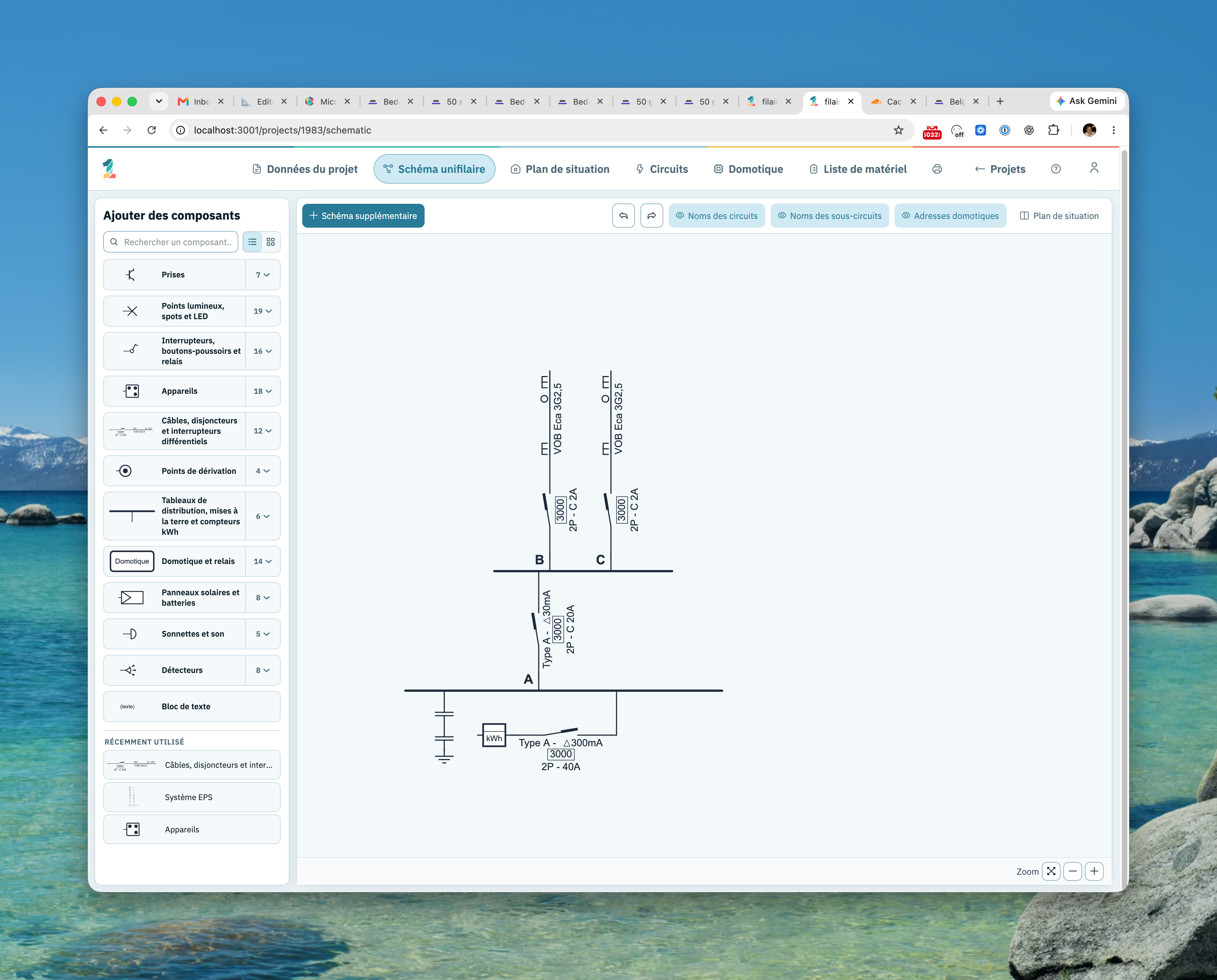
This is the heart of the drawing: a distribution board with a transfer module on it, an inverter with a backup output, and the connection between the two. You can do this in two ways — the result is identical, only the number of steps differs.
Choose one of the two ways:
You build the setup yourself, component by component:
Choose this when your setup differs from the standard case and you want to define every component yourself.
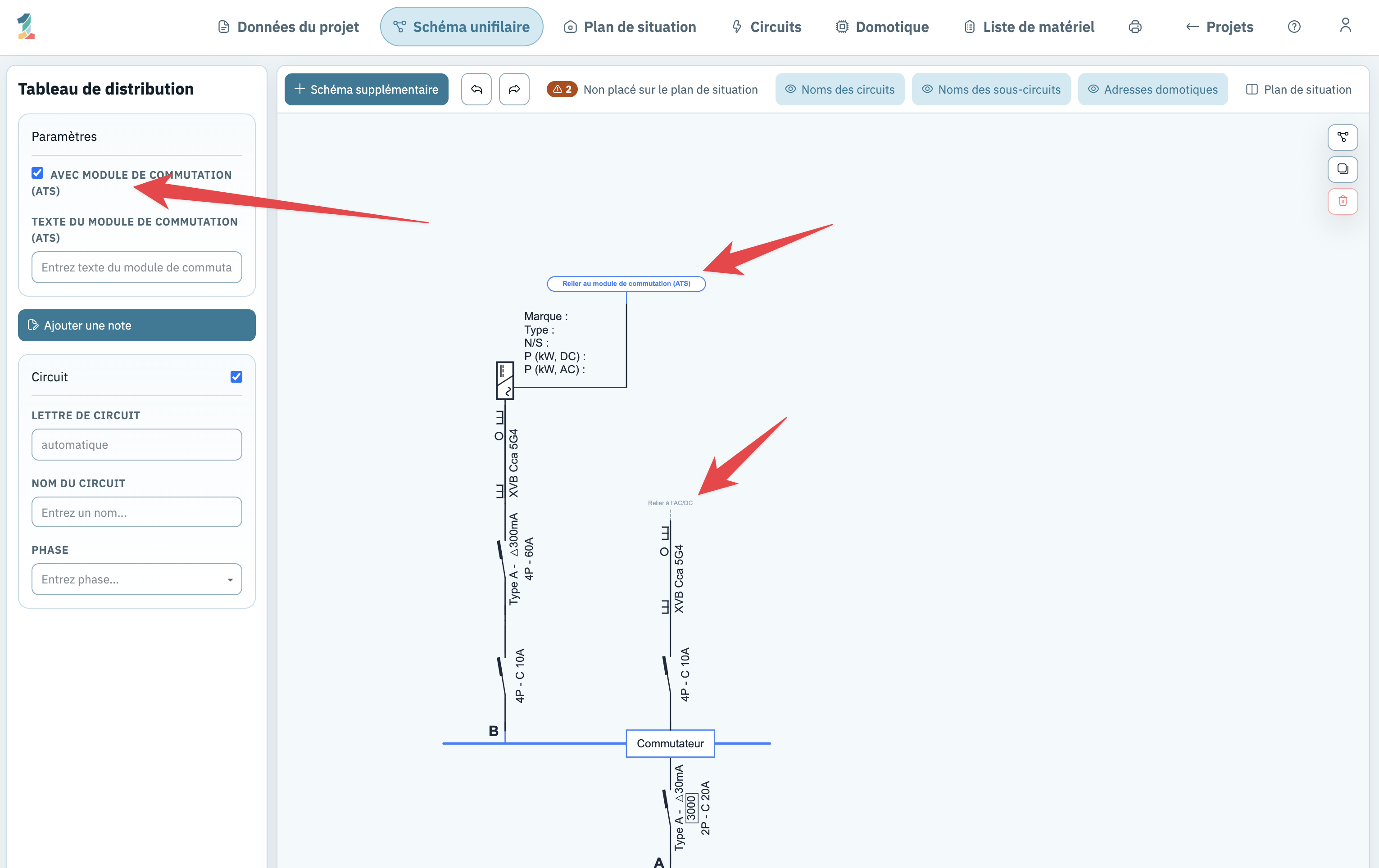
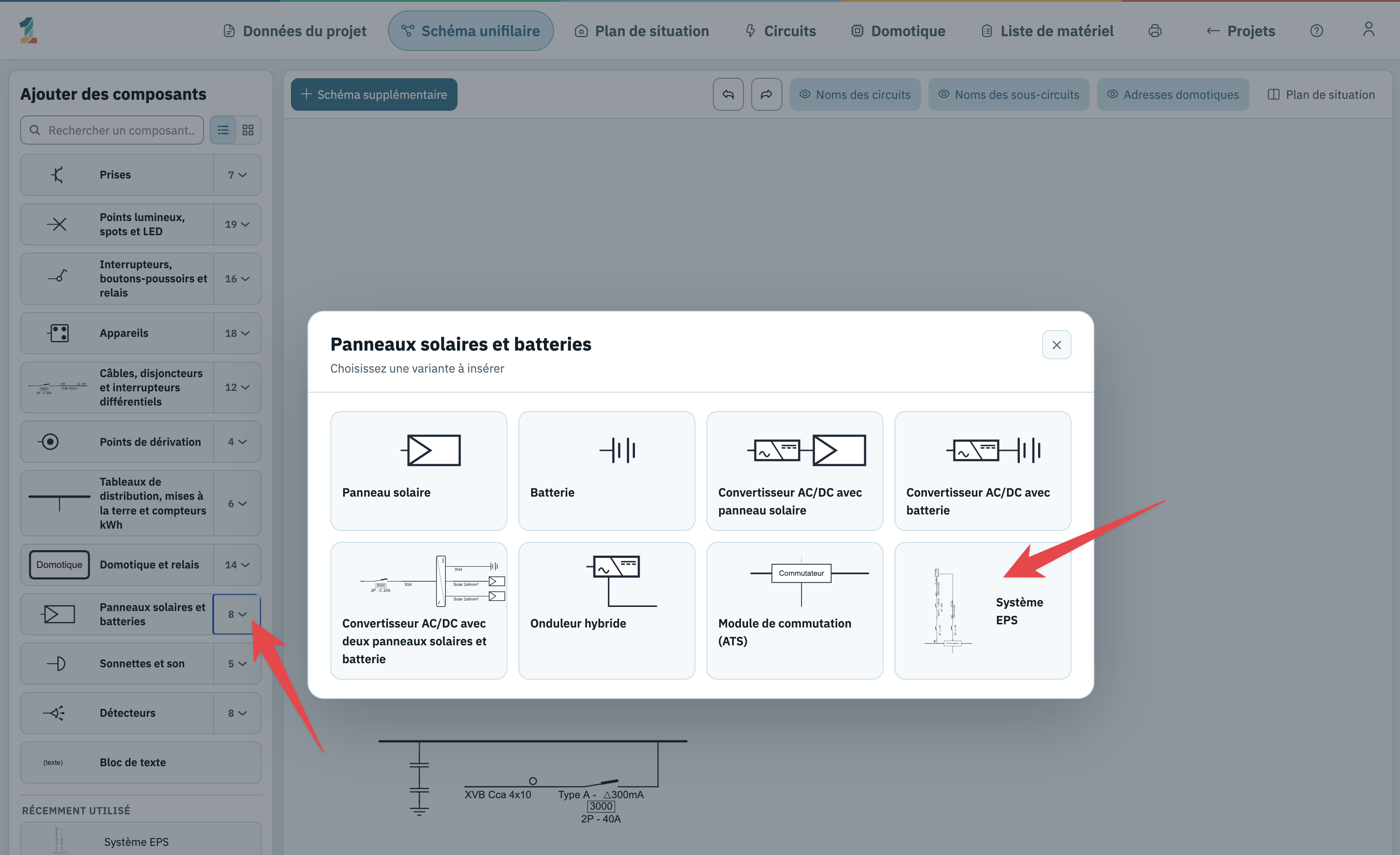
Drag EPS system from the group Solar panels and batteries onto the diagram. That one symbol places the complete setup:
Choose this when you draw a classic setup. Everything is in place in one action; afterwards you only adjust the values.
Whichever way you chose, the values still have to match your installation. Click each component and fill in what is actually being installed. What 1wire fills in by default are starting values.
With the backup power on the diagram, you complete the rest of the installation as you normally would.
Now come the circuits that must keep working during a grid outage. Everything you place on the rail of this board sits behind the transfer module. When inserting, 1wire shows the insertion points to the left and right of the module, so you keep the inverter supply visually separate from the regular circuits.
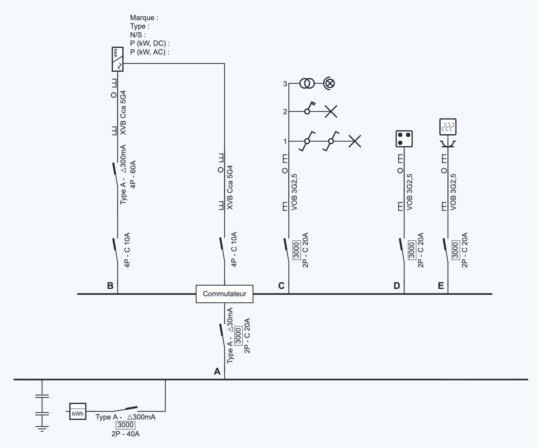
Then give each circuit a clear name via Circuit names. It takes two minutes and saves discussion at the inspection.
Open the circuit list and the material list. Both are built automatically from your diagram: the transfer module, the inverter, the battery and the solar panels are listed straight away, along with the cables of the backup branch. If something isn't right, you adjust the diagram and the lists follow.
Then you print the complete file as a PDF: single-line diagram, floor plan, list of circuits and material list.
View a material list in the demo project →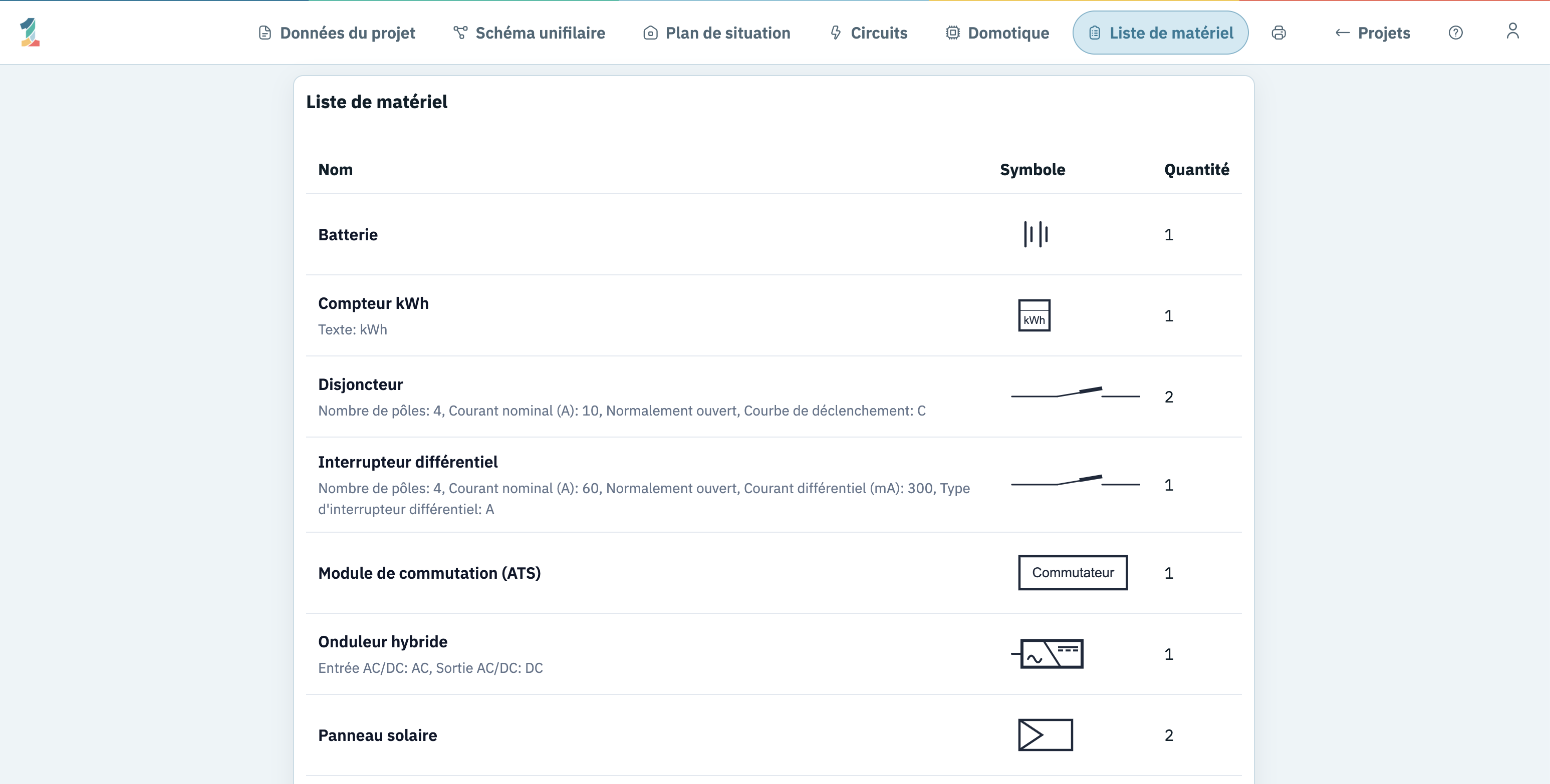
EPS stands for Emergency Power Supply: the inverter's backup power function, which keeps a separate output live during a grid outage. If you chose the second way in step 2, this one library component places more than just a board and an inverter. Here's what's included, and what you should definitely check:
All those values are starting values, not advice. Go through them one by one in step 3 and match poles, amperage, residual current and cross-section to the installation you are actually installing.
Try it yourself in the editor →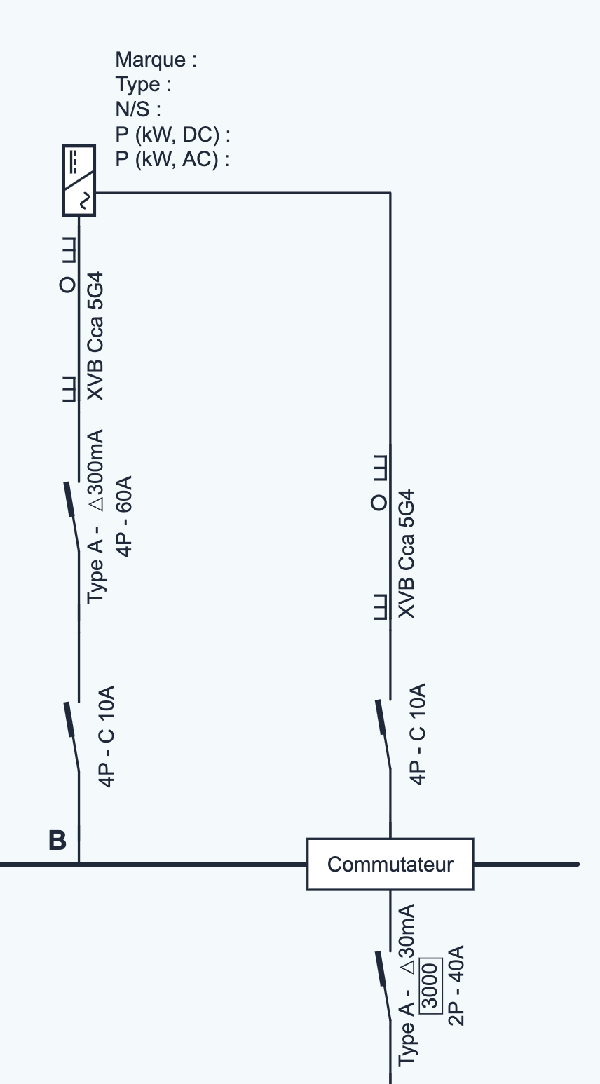
Since 1 April 2026, Book 1 of the AREI explicitly takes into account DC systems — storage batteries and photovoltaic panels — and installations fed by multiple sources. Since then the regulation also consistently speaks of an energy source where it used to say “power supply source”. Three provisions from Book 1 relate directly to what you draw on this page:
The control devices that ensure the changeover of energy sources act on all live conductors and must not connect these sources in parallel untimely. (unofficial translation)That's exactly what a transfer module does.
Devices are provided that allow the energy source to be separated. (unofficial translation)
fed by energy sources in parallel, for example the public distribution grid and an autonomous energy source, protection against electric shock in case of indirect contact is ensured in both cases: with all sources together and with only one of them. The same subsection states that the proper operation of the protective devices must not be adversely affected by
DC components originating from static converters or filters.
Source: Royal Decree of 6 October 2025, articles 21, 43 and 44 (Belgian Official Gazette 29 October 2025), in force since 1 April 2026. This summary is for guidance only; its application to your installation remains the responsibility of the installer.
Drawing a battery and an inverter is not the same as drawing backup power. Without a module and without a backup connection, nobody can tell from the diagram what happens during a grid outage.
Solution: put the transfer module on the board and connect the backup output.
The regular AC/DC symbol has only one output. So you never get a backup connection out of it, and the diagram suggests an installation without backup supply.
Solution: use Hybrid inverter
The connection between the inverter and the module is a real cable with real protection. If it stays empty, the diagram lacks exactly the data an inspector looks at.
Solution: add a circuit breaker and a cable, with number of conductors and cross-section.
With backup power the question is always: which circuits keep working? Without circuit names the reader has to puzzle it out from the diagram.
Solution: name your circuits and include the list of circuits in the printout.
Draw for free in your browser, without installation. You only pay when you want to print the plan without restrictions.
Your single-line diagram should reflect the installation as it was actually built. A hybrid inverter, the associated module and the circuits behind it are part of that. Anyone reading the diagram must be able to see where the second energy source is and how it is protected.
The regular AC/DC symbol has one output. The hybrid inverter has two: a regular output and a separate backup output. Only that second output can be connected to the transfer module.
Select the inverter or the module. 1wire then shows the button “Connect to transfer module (ATS)” on the drawing sheet. One click makes the connection; “Disconnect transfer module (ATS)” undoes it. As long as there are still components on the branch, 1wire asks you to remove or move them first.
Yes. A distribution board with a transfer module counts as a device and therefore appears in the material list. You can also place it on the floor plan, just like your other devices. A distribution board without a module is only a drawing convention and doesn't appear in the list.
Yes. Everything you place on the rail of the board with the transfer module sits behind that module. You decide how many circuits that is and on which side of the module they appear in the diagram.
No. You can start drawing in the browser straight away. When you're signed in, your projects are saved online automatically and you can open them on all your devices.